 Crazy Electrical
This article is about a diode power mixer circuit.
The circuit shown in this article is not the best way to mix two or more power signals. An alternative circuit is shown in this link:
https://electriccircuits.yolasite.com
I used the following diode IC (integrated circuit):
https://www.digchip.com/datasheets/parts/datasheet/513/MBR1545CT-pdf.php
Step 1: Design the Circuit
I have drawn the circuit in PSpice student edition simulation software:
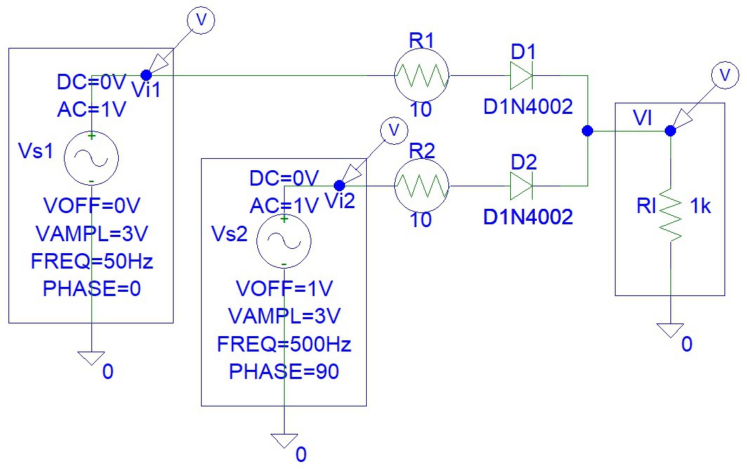
The drawing above is not showing the dual Schottky Diode IC (integrated circuit) that I used instead of two diodes (D1 and D2), because the student edition does not have this component in the list. Schottky diodes have lower forward bias voltage drop than typical silicon, germanium, or point contact diodes.
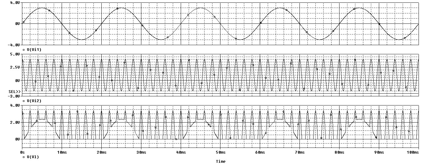
Step 2: Simulations
Simulations show how the circuit will work:
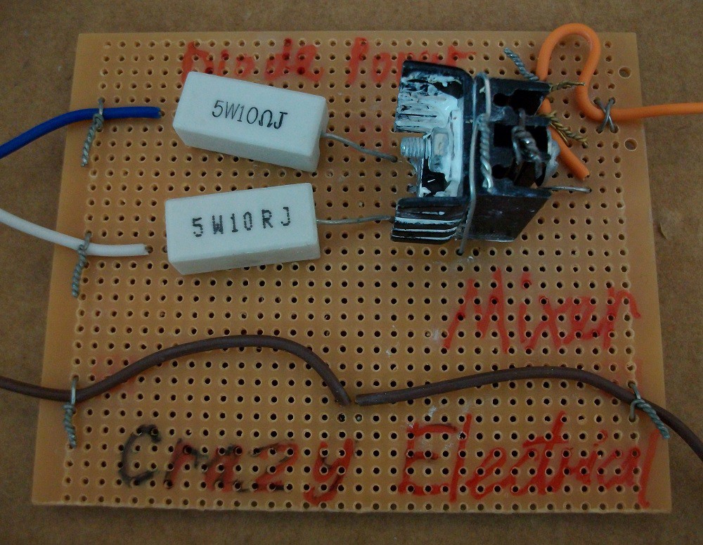
Step 3: Make the Circuit
I used soldered the components onto the matrix board:

Step 4: Testing
I used a benchtop signal generator (for the first channel), 8038 signal generator circuit (for the second channel), and Instrustar USB oscilloscope for testing.
Input signal:
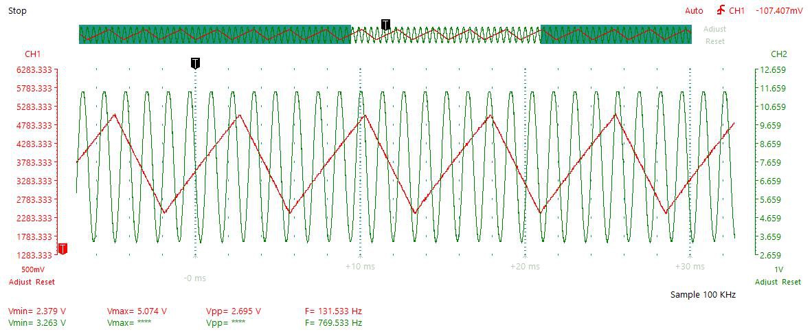
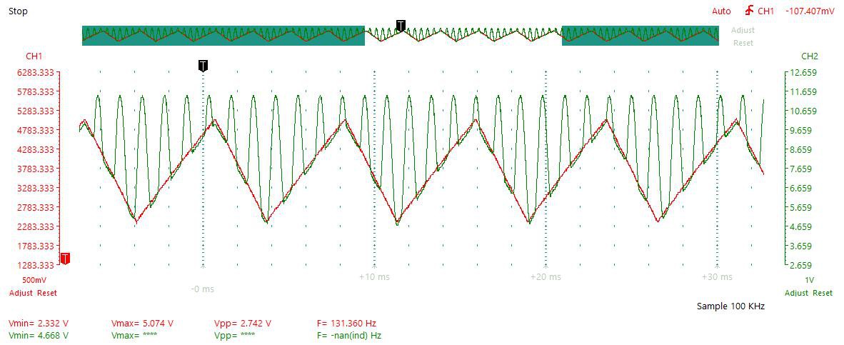
Triangle and Sine Wave:
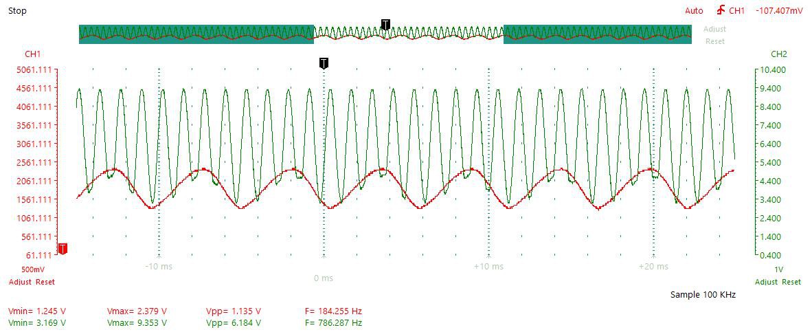
Two Sine Waves:
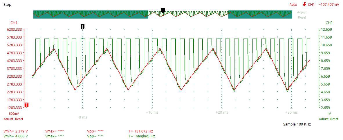
Triangle and Square Wave:
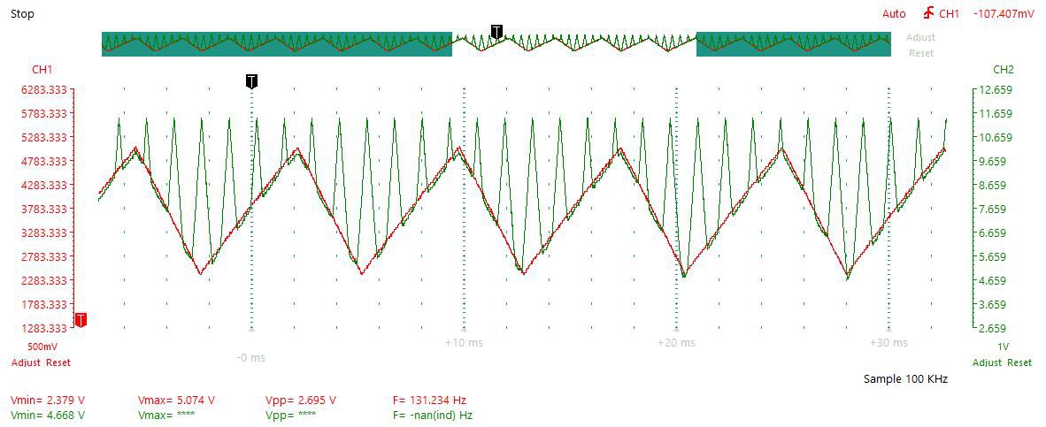
Two Triangle Waves:
Conclusion
There is an option of eliminating the DC component with the RC (resistor-capacitor) high pass filter. However, this is not a good idea if you are making a power supply.
References
Discussions
Become a Hackaday.io Member
Create an account to leave a comment. Already have an account? Log In.