robert.c.baruch
-
Transformer part 2
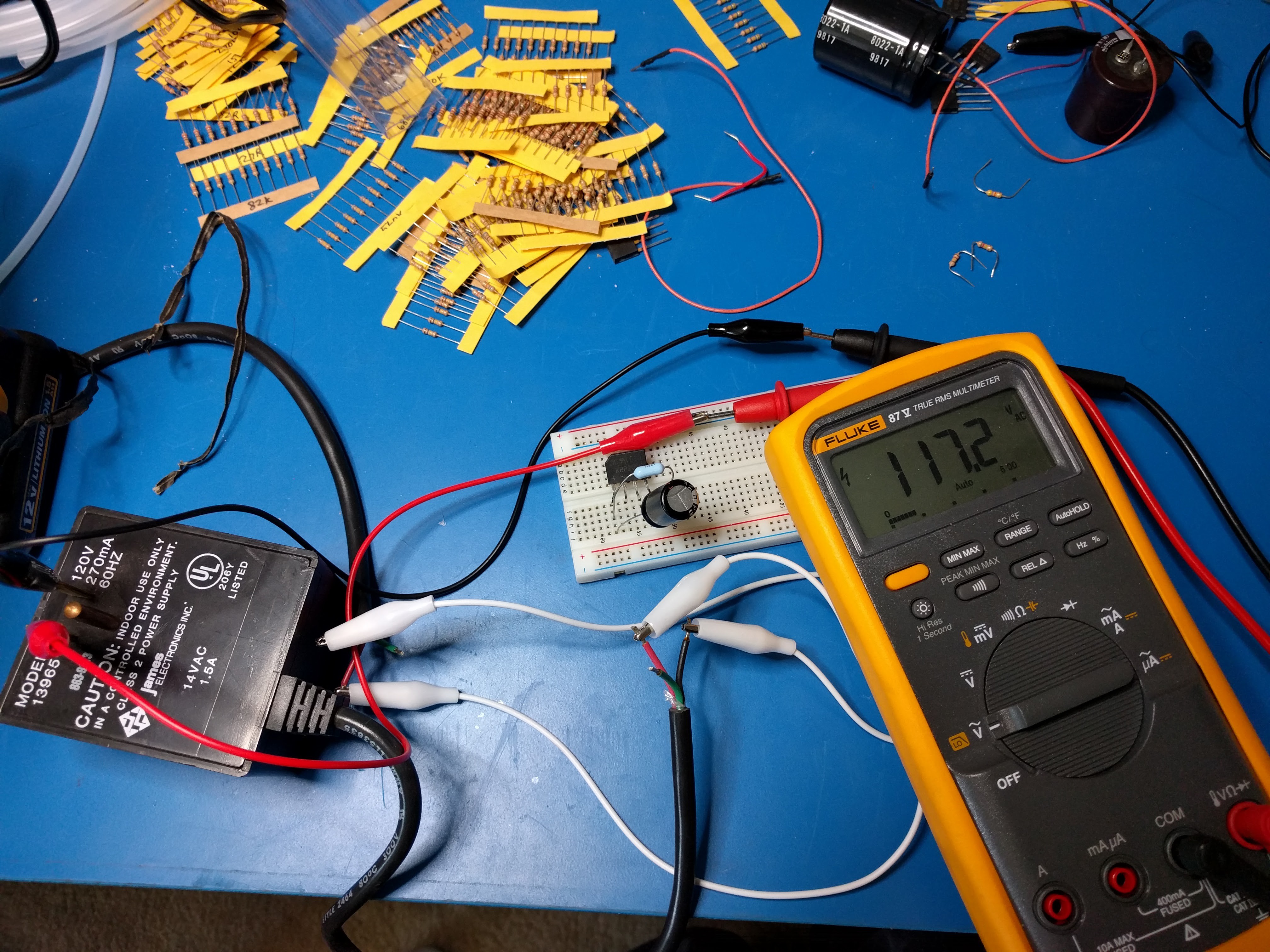
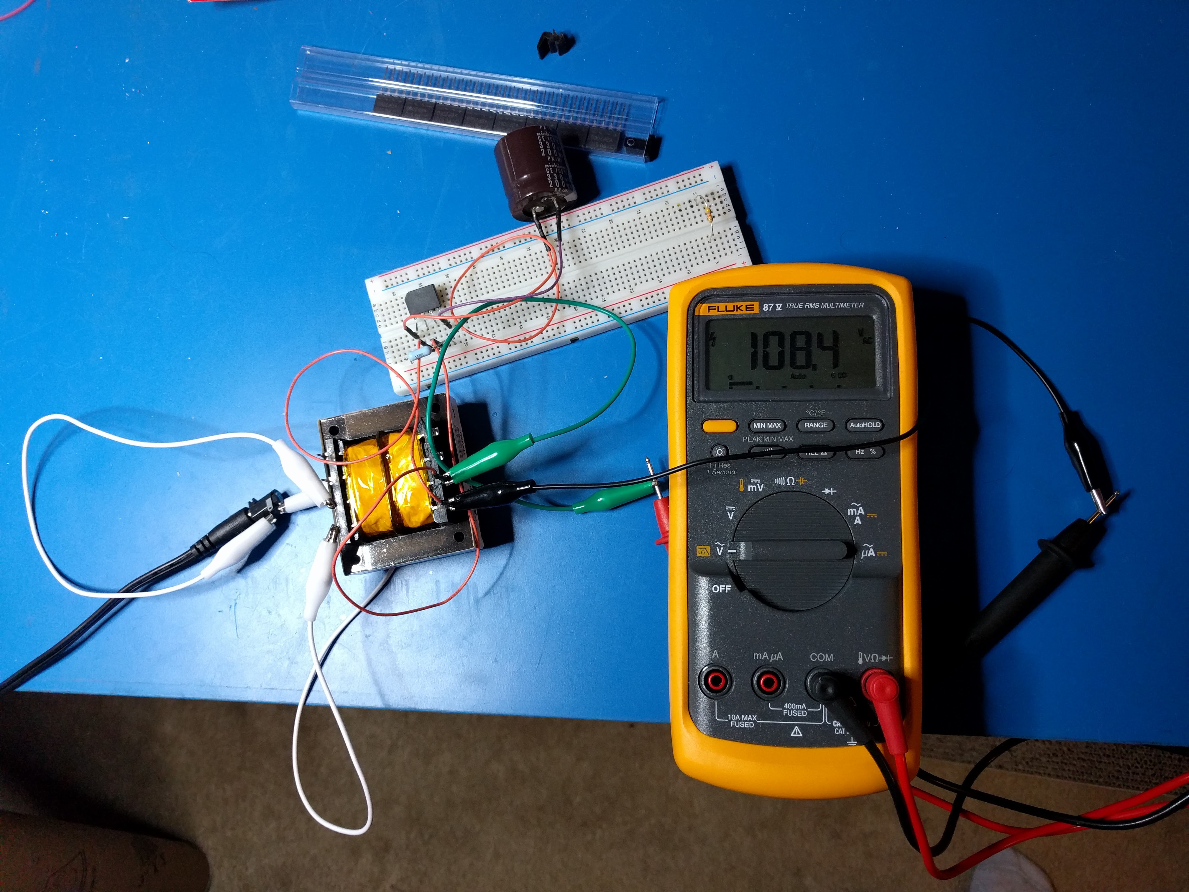
04/30/2016 at 22:27 • 0 commentsWent to surplus and got two of the same AC/AC adapters: 120VAC to 14VAC @ 1.5A. I hooked them up back-to-back to see what came out. With 121VAC coming from the wall, I got 16VAC from one transformer, then hooking that to the other transformer, I got 117VAC back out. A 3% loss, which is okay.
![]()
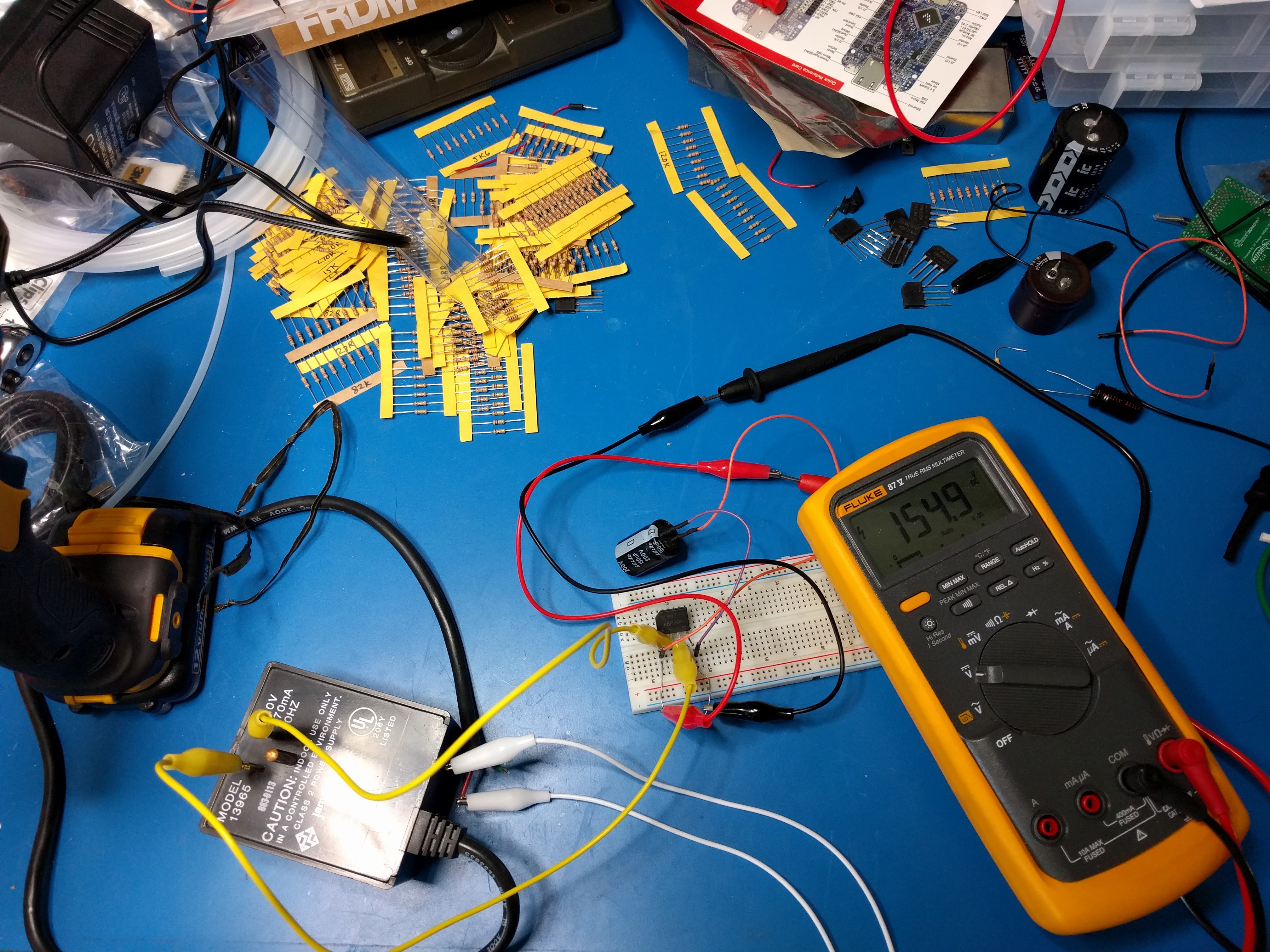
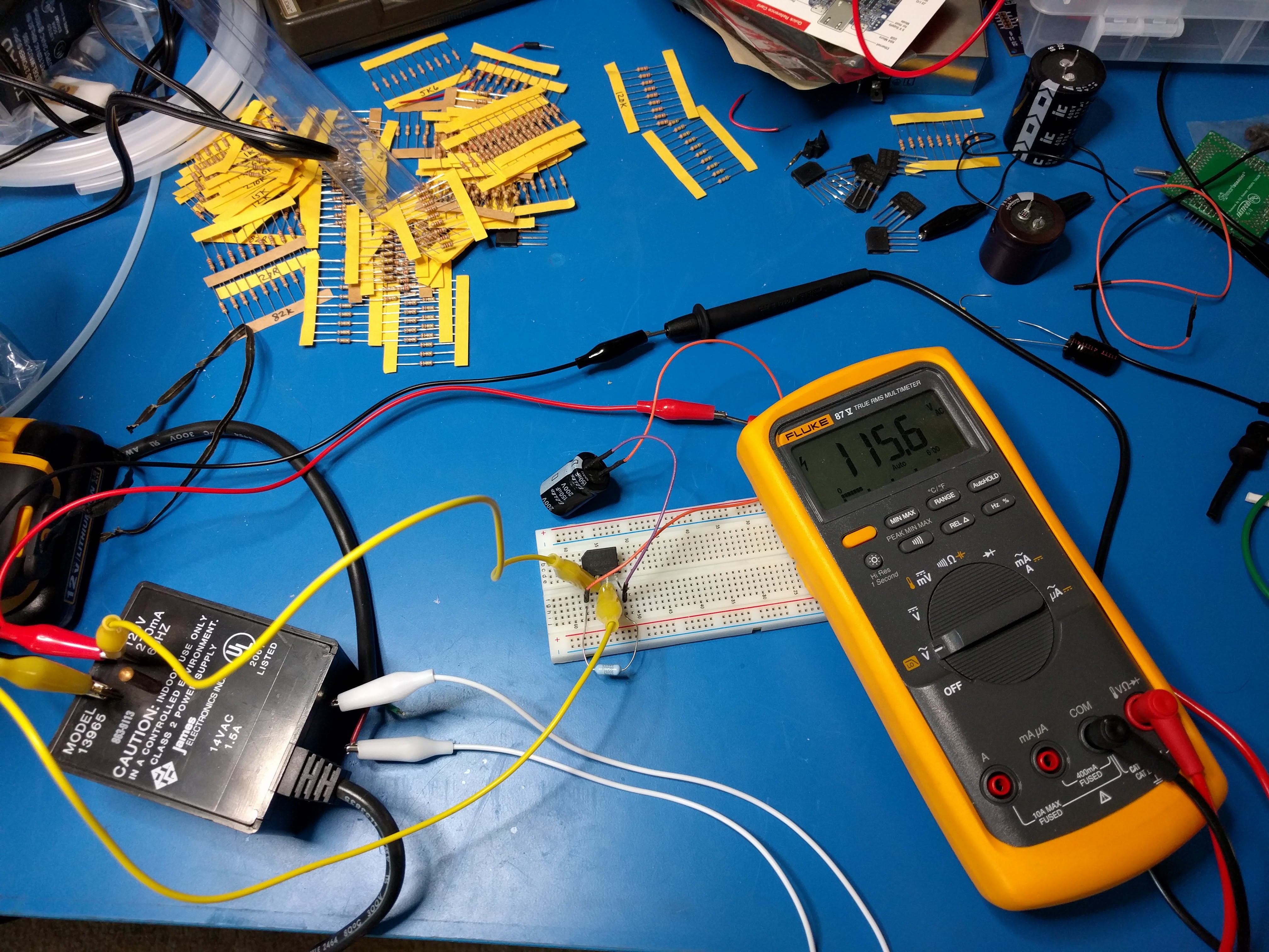
Now, in theory, 117 x 1.4 = 164, so I should expect about 162VDC out, assuming 2V diode drop. In fact, I got 155VDC. Measuring the AC input, I found it had dropped to 115.5VAC, which should have translated to about 160VDC. So we're still losing power somewhere.
![]()
![]()
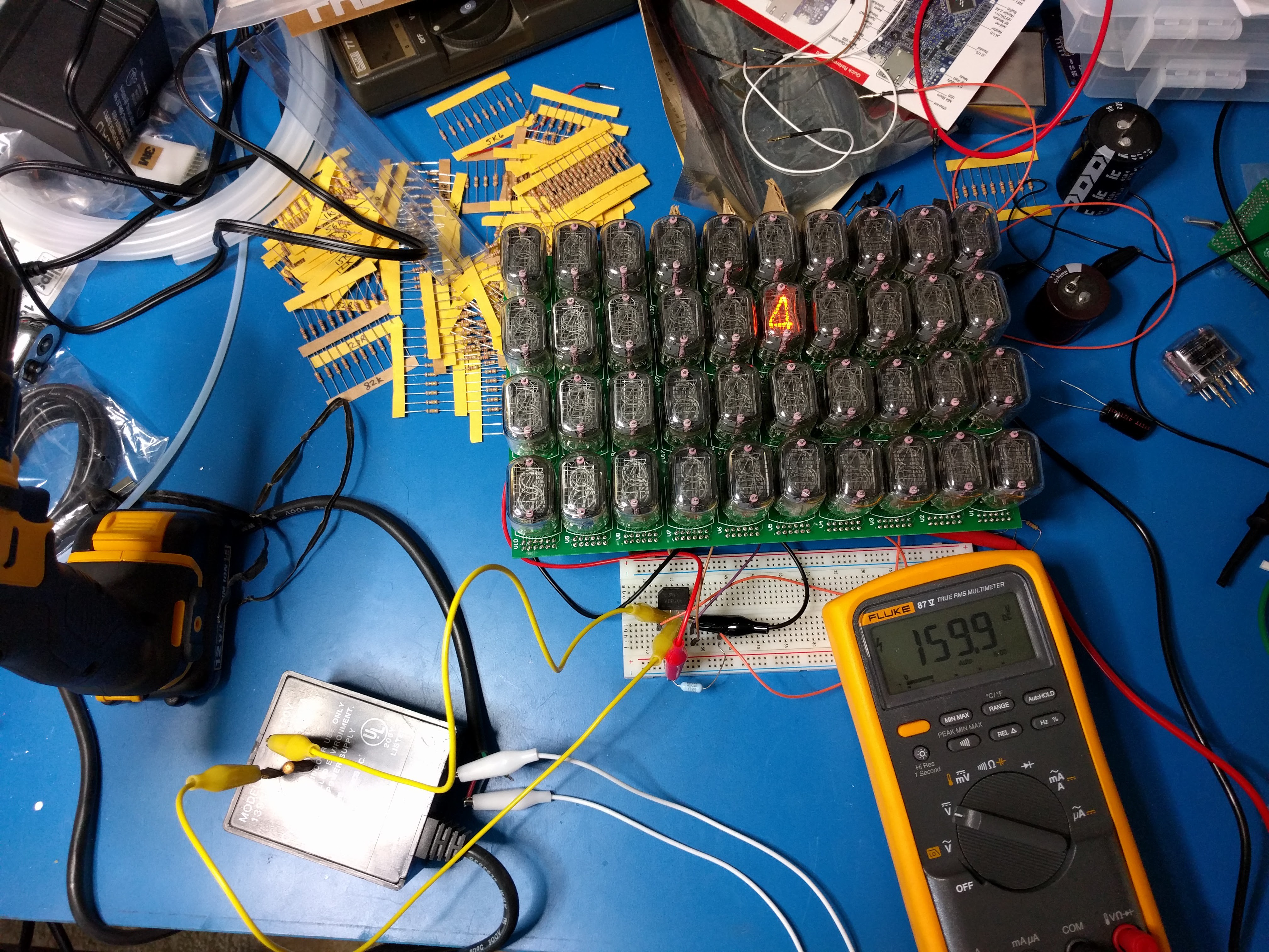
Well, okay, let's decide to live with this and see if we can light up a Nixie.
![]()
Yes. Apparently we can. And interestingly enough, the DC voltage is now 160V, but then we are drawing less power. Which brings up the question: can we load this power supply down with the full 150mA or so? To do this, I'd need about 1k @ 25W, so another trip to surplus is called for. On the other hand, the transformers are rated for 21W, so perhaps the best I'd be able to do is 1.2k @ 21W. We'll see.
-
Transformer. Wat r u doing. Stahp.
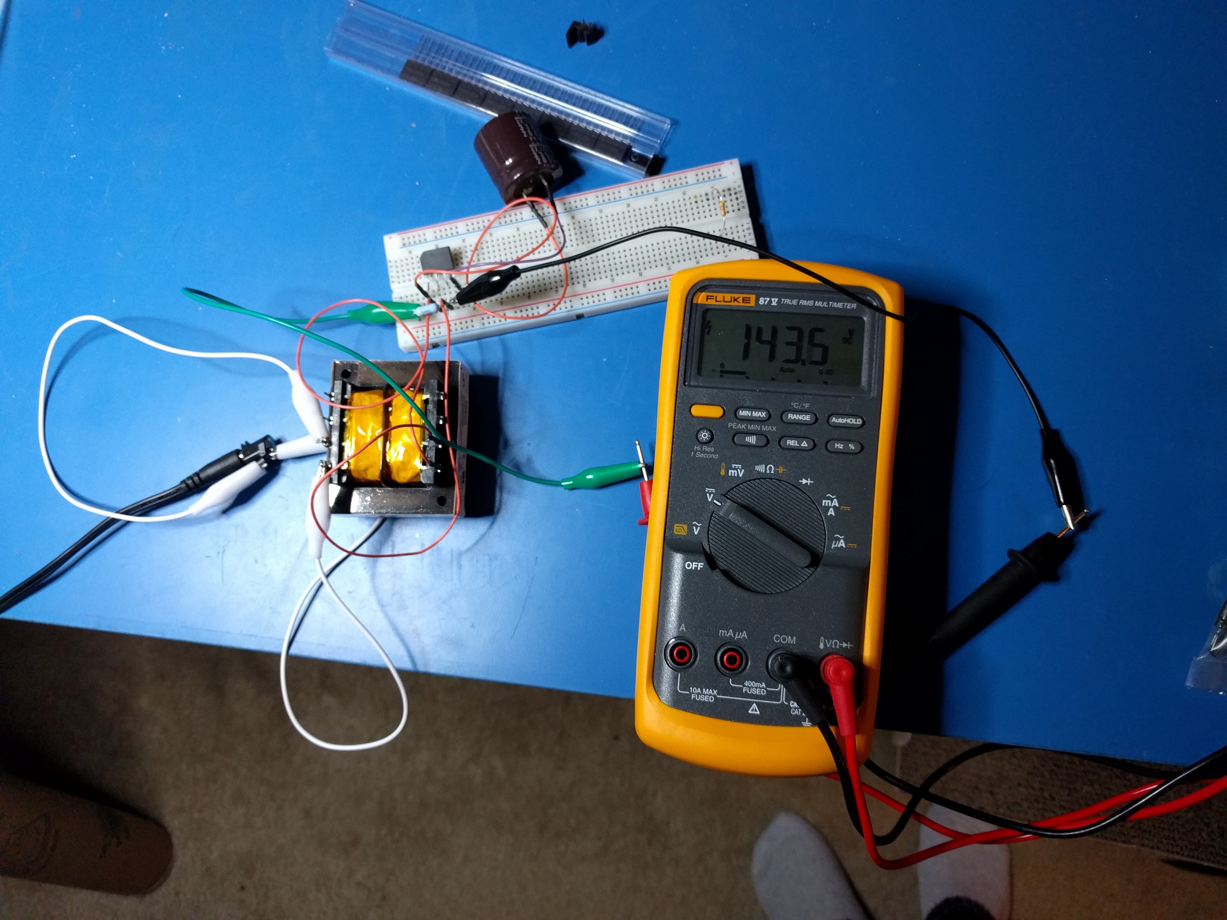
04/30/2016 at 02:34 • 0 commentsI have a 115VAC primary 24VAC secondary transformer. I thought that if I put 24VAC into the secondary, I'd get 115VAC out. I got 108VAC out:
![]()
Ok, that's not too bad, 6% off. But I thought that rectifying would give me 108 x 1.4 = 151VDC. Instead I get 144VDC? I do expect some small amount of drop due to the diodes in the rectifier, but it's at most 2 volts.
![]()
The rectifier (KBP206G) is being loaded down with a 22.5k resistor and a 330u 200V capacitor.
I checked the input voltage: 26.7VAC. I removed the resistor: 148VDC. I put the resistor back and used a larger capacitor. 142VDC.
I observed the primary (108VAC) waveform and saw some clipping, which would explain why the reduced DC. I removed the rectifier and the clipping went away. I don't thing this is transformer saturation, since there's no DC across the transformer, and I'm barely pulling any power out of it.
I'm not sure what that's all about. So I ordered a few different transformers, and I'm going to try those to see if it's something systematic that I'm just not understanding.
-
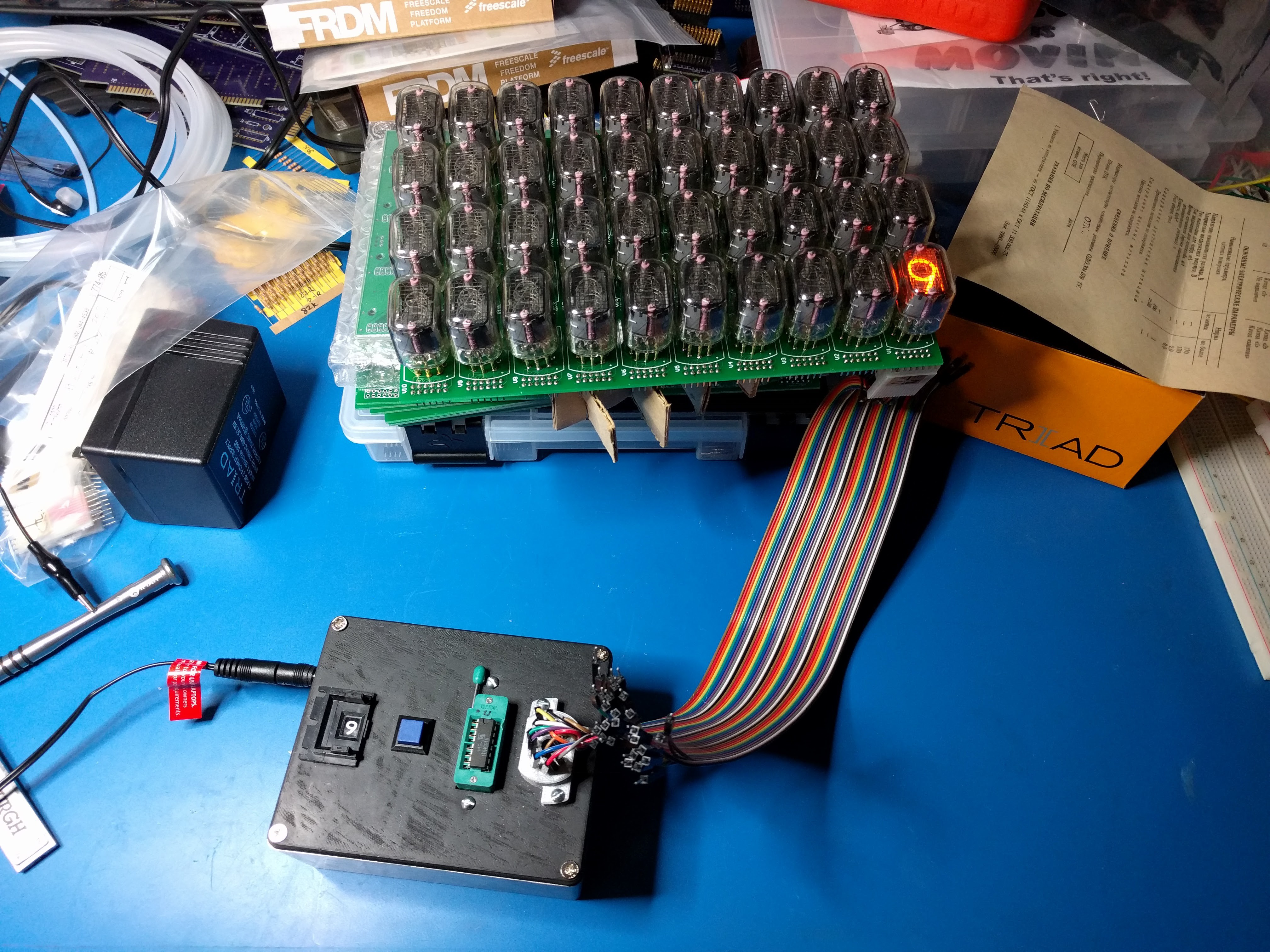
Testing the Nixie display board
04/29/2016 at 02:49 • 0 commentsEverything you build should be tested somehow. Otherwise you put five things you built together and they don't work, and now you need to test them anyway.
So when I put together a Nixie display board, I needed to make sure the things still lit up according to the pins as expected. I just took the manual Nixie tester and this unbelievably inexpensive and awesome ribbon cable, added an IC test clip, and tested away.
Why not a female 2x6 header? Because they are too tight to quickly put on and remove. When you're testing 50 connectors at a time, you don't want to spend five seconds struggling to pry each connector apart.
The IC clip was made to go on IC's whose rows are 0.3 inches apart, not 0.1 inches like the headers. So, I had to take it apart, dremel out the plastic stop, put it together, and it worked great.
![]()
![]()
-
Testing Nixies
04/27/2016 at 03:22 • 0 commentsSo you got a few 50-packs of Nixies from Russia. How do you test them?
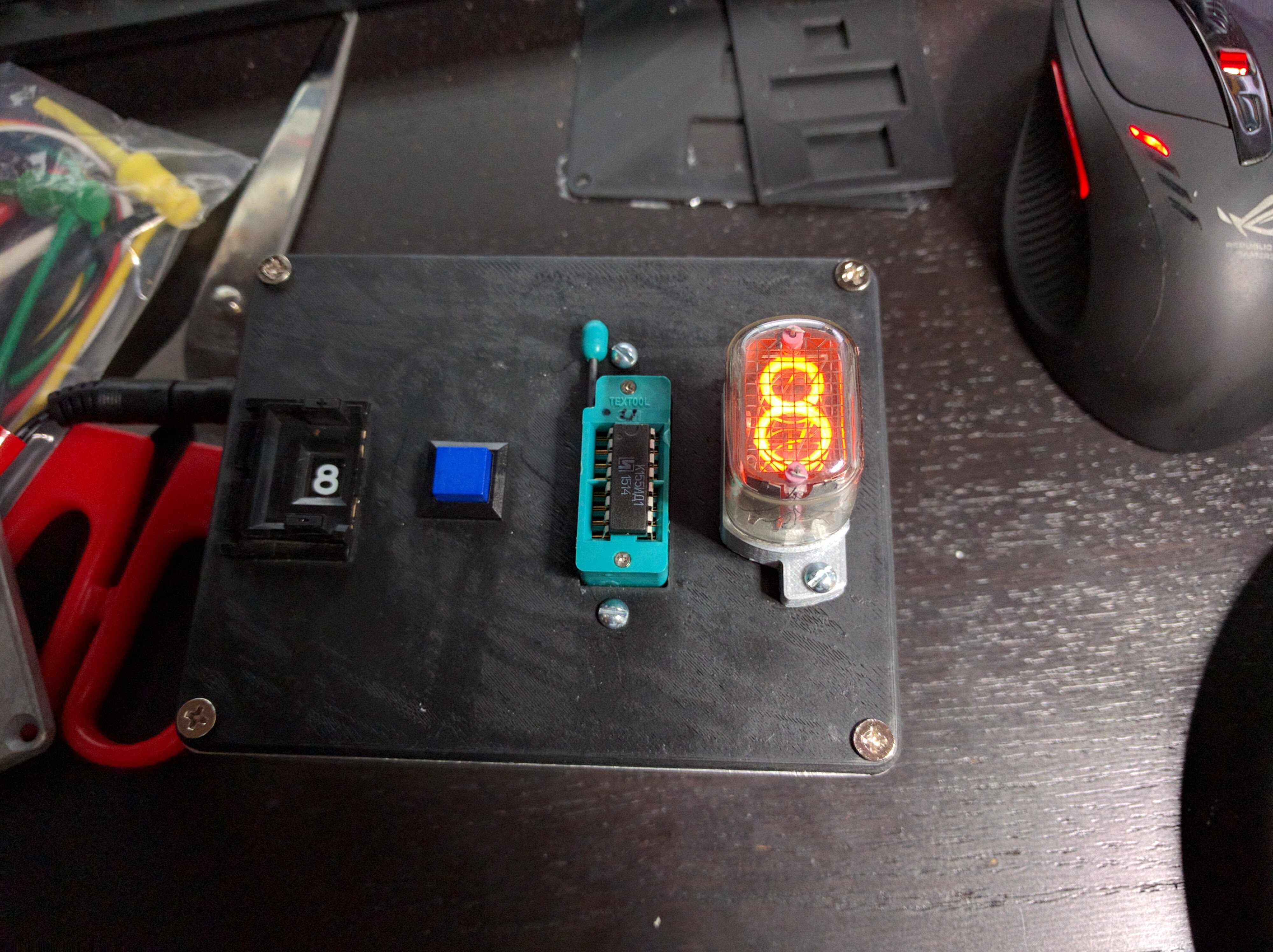
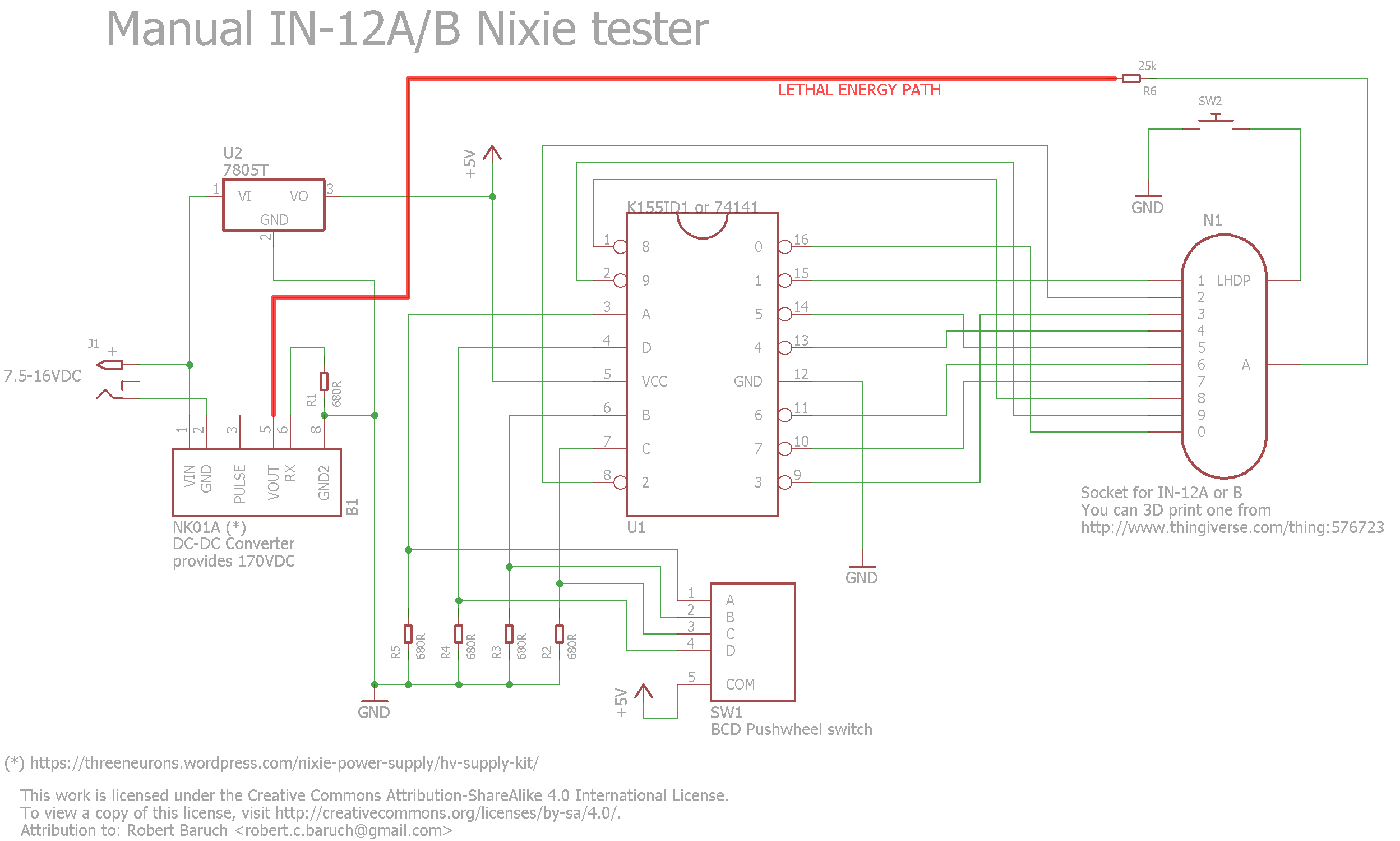
With this manual Nixie tester.
![]()
It operates from any power supply 7.5 - 16VDC. The button is to test the dot segment.
To build this, you will need:
- Wall-wart 7.5 - 16VDC out, maybe 20mA minimum
- BCD pushwheel (such as Omron A7D-106-1)
- Pushbutton (normally open)
- K155ID1 or 74141 IC
- 16-pin ZIF or DIP socket (recommended, for the K155ID1 in case yours is a dud and you need to replace it)
- IN12-A/B socket (you can 3D print one)
- 7805T 5v linear voltage regulator
- 12x 1-mm pins scavenged from a D-sub connector, for the 3D-printed socket
- 5x 680-ohm resistors
- 1x 25k resistor (value not important, +/- 5k is fine)
- NK01A HV power supply kit (it's a compact DC-DC converter for tubes)
I would just build this on a perfboard, it's not really worth making a PCB.
WARNING! The output from the NK01A is lethal. That is, it can source an energy of over 13.5 W-sec over three seconds. Be very careful:
- When working with the power on, always keep one hand well away from the circuit.
- When working with the power off, make sure the power is unplugged, use one hand to short the supply's output to ground (to discharge any capacitors). Then measure the output of the supply with a meter to be sure it's dead.
- An enclosure is recommended so you can handle the entire thing safely with the power on.
![]()
-
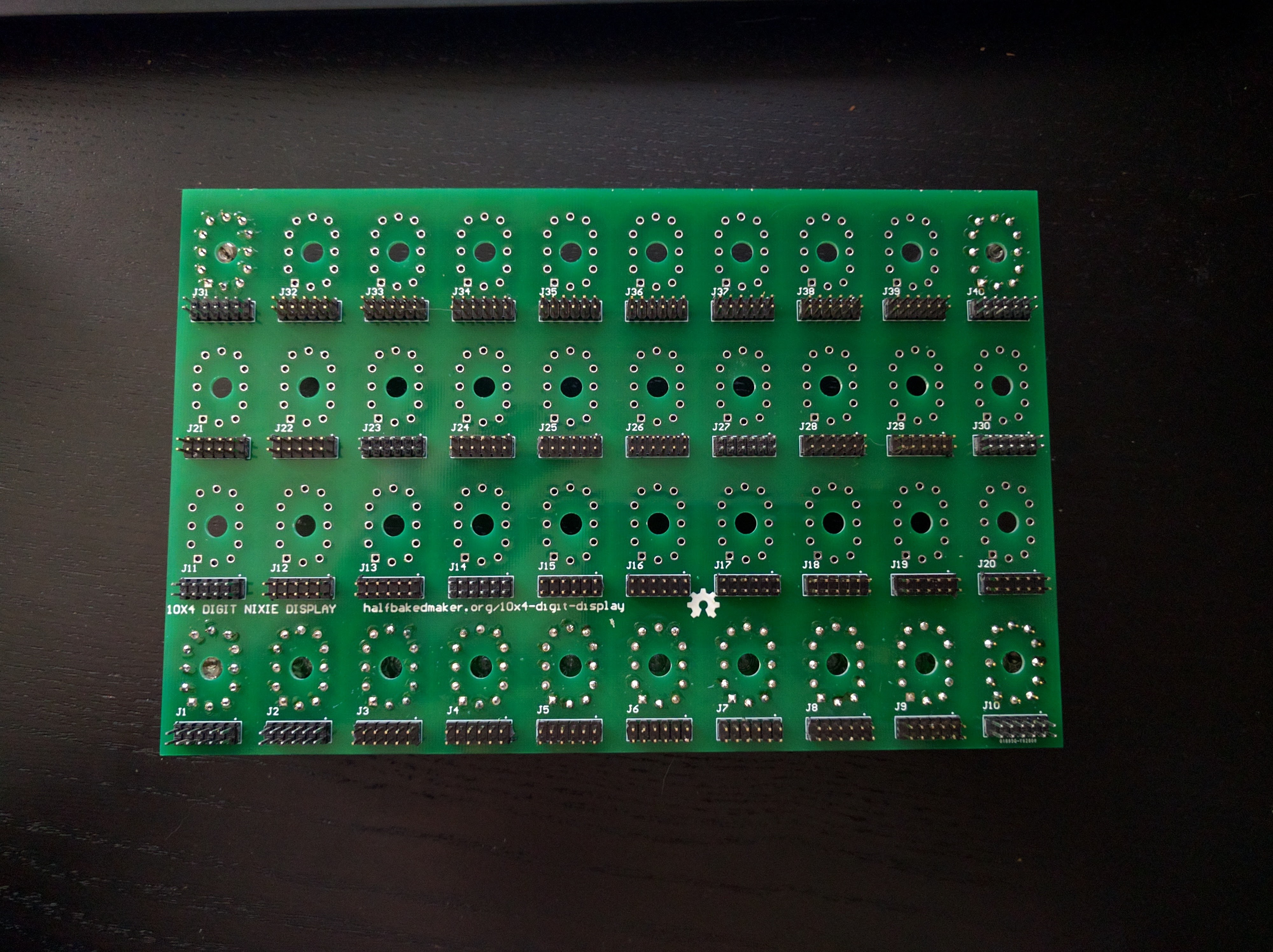
The display board
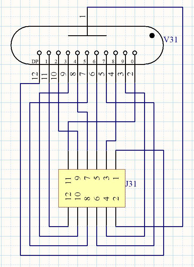
04/26/2016 at 02:49 • 0 commentsThe Nixie display board is a 10x4 matrix of IN-12B (ИН-12Б) Nixie tubes. Each tube has a 6x2 male header, where one pin is for +170VDC and 11 data pins are for the digits plus the dot. You keep all the data pins above 120VDC to keep the digits off, and pull one down to ground to turn it on.
The tubes are on one side, and the headers stick out the other side where they can be connected to drivers.
Since the calculator will have 20x4 tubes, we need two of these.
Here's the schematic for one of the 40 tubes:
![]()
I wired things up cleverly so that power was delivered in one corner, and then starting from the opposite corner and working your way back and forth, you have the pins for digits 0, 1, 2, ..., 9 and then the dot. The numbering of the pins on the header looks weird because the component is a mirror image: it goes on the bottom of the board.
I did the schematic and layout for the display board in Altium's Circuitmaker — I'm more used to Circuitmaker's routing than Eagle, but I'm also learning about routing in Eagle. Similar to Eagle, a component is a schematic symbol plus one or more board layouts. So I defined an IN-12B component and used that. I generated the Gerbers, and sent them off to Seeed Studio because they are far cheaper than OSHPark for larger boards. Each board is 8 1/2" x 5 1/2" (215 x 140 mm).
Next, I populated and soldered the headers.![]()
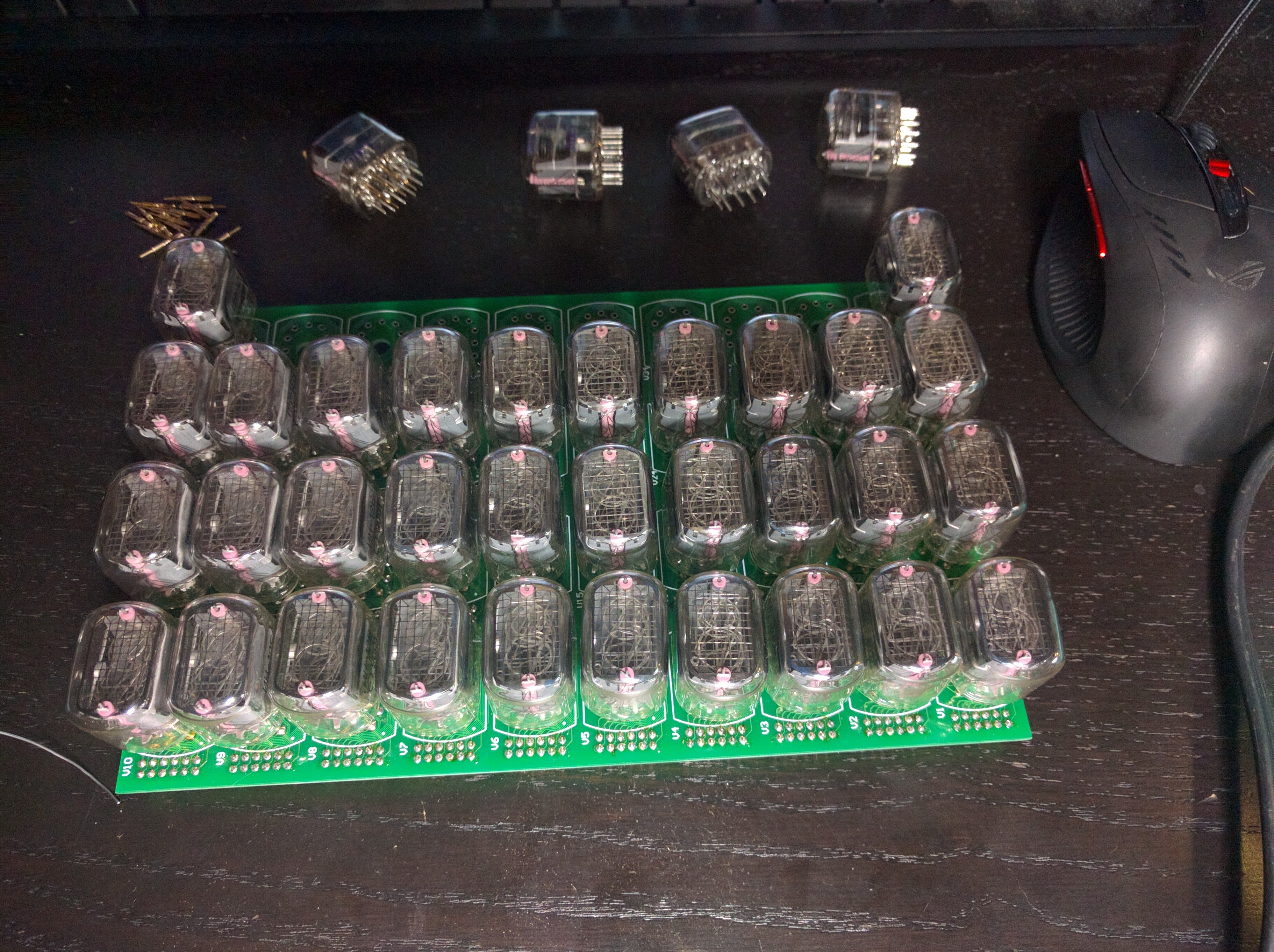
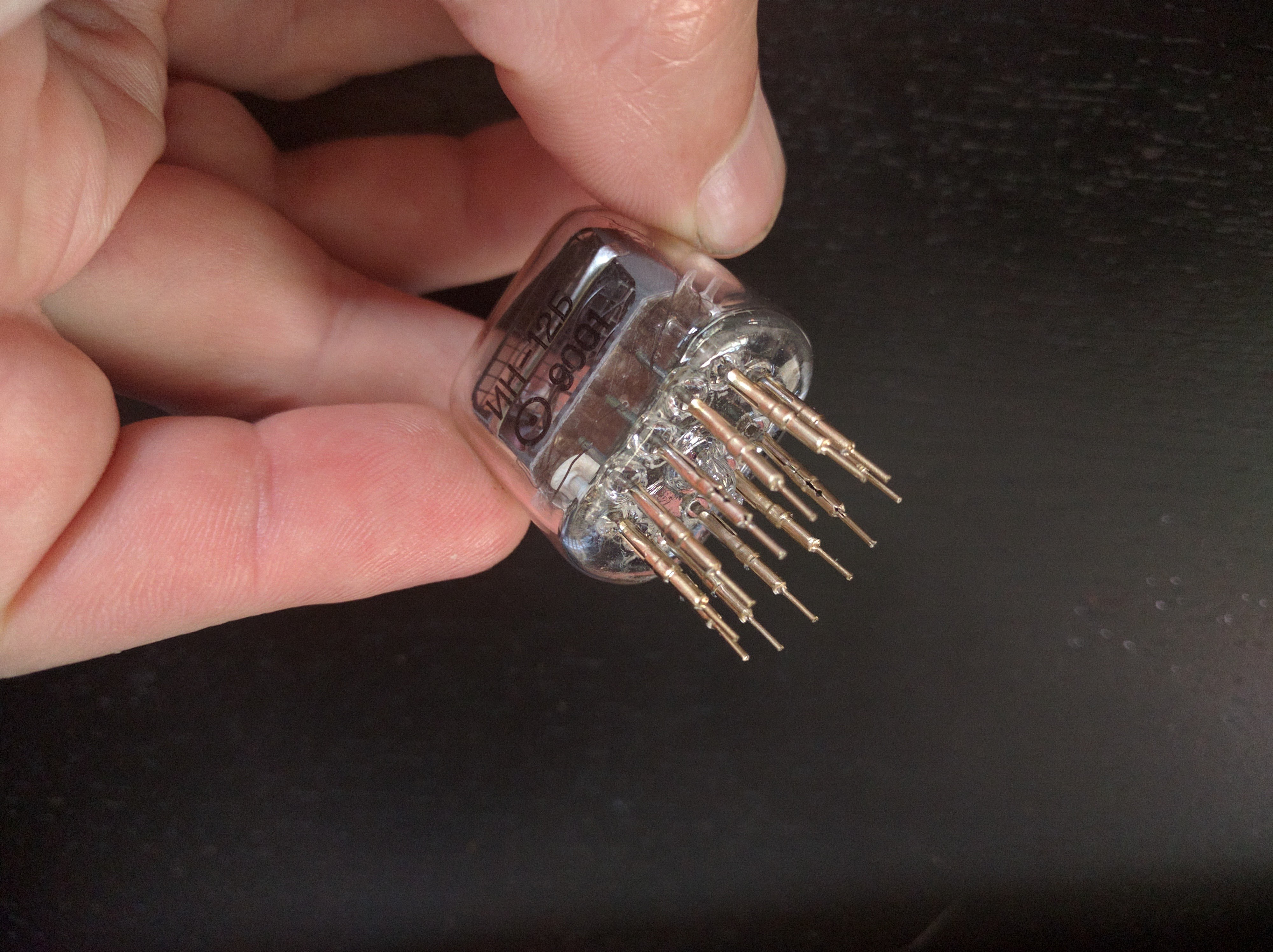
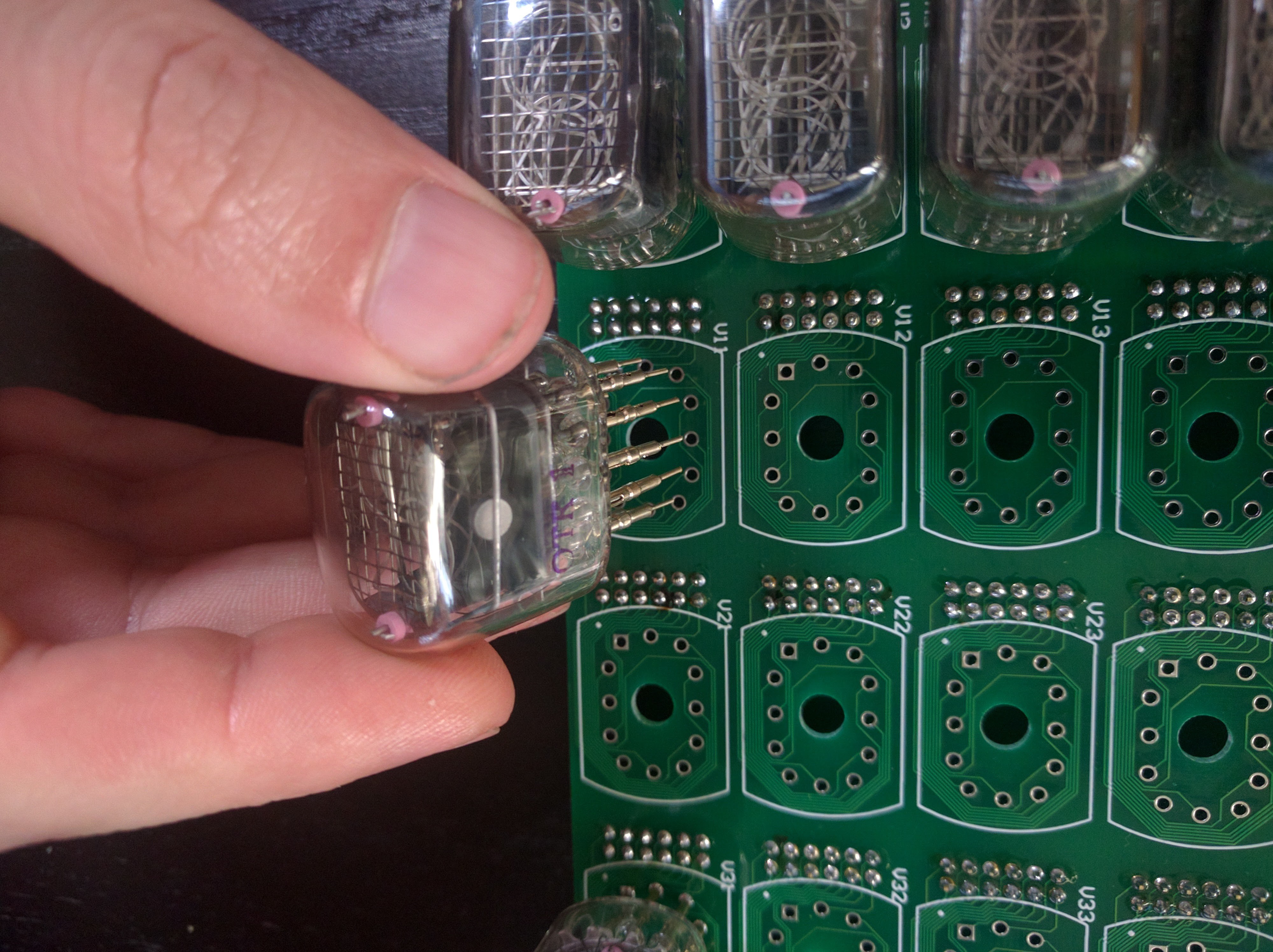
The next step is to take one tube and stick onto it 12 1-mm pins scavenged from D-sub connectors. Then insert the result into one of the positions on the PCB. Notice that inside the tube, one of the pins is white. This is the +170VDC pin. Make sure that pin goes into the square pin 1 on the PCB.![]()
![]()
![]()
![]() I put the initial four in at the corners, covered with a piece of cardboard, flipped the whole thing over, and soldered them in. This helps keep the tops of the tubes at the same level. Then keep going, doing four or five at a time.
I put the initial four in at the corners, covered with a piece of cardboard, flipped the whole thing over, and soldered them in. This helps keep the tops of the tubes at the same level. Then keep going, doing four or five at a time.![]()
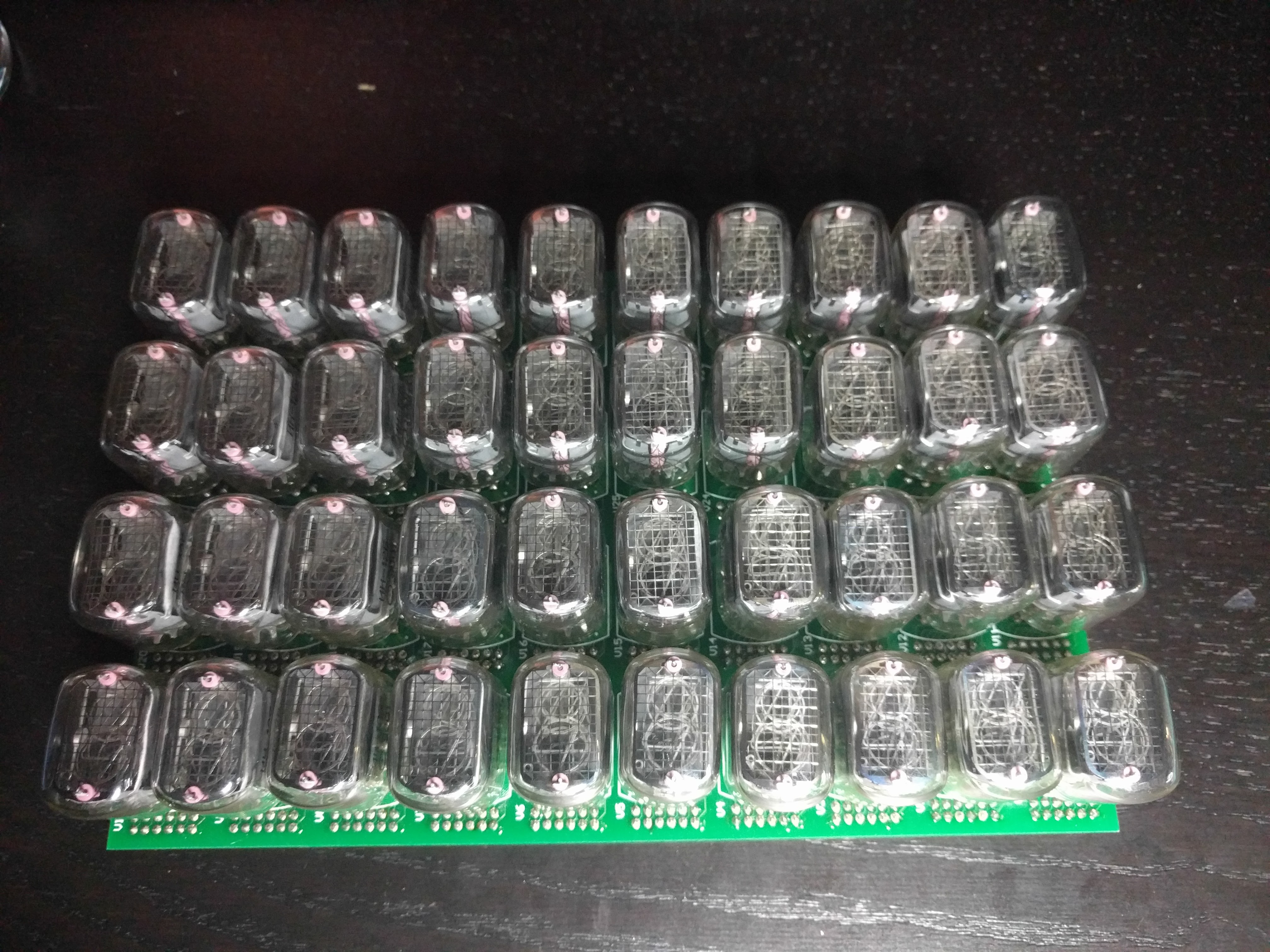
Watch a few episodes of Walking Dead or Supernatural while you do this. It helps. And before you know it, you're done!
![]()
-
Will this thing kill you?
04/19/2016 at 05:25 • 0 commentsImagine some awesome person builds the calculator. They're messing around inside under the worst possible circumstances. Specifically, the power is still on, using both hands, one poking with a metal-handled screwdriver and the other touching ground. Also, they're hot and sweaty and in Florida on the most humid day ever recorded.
Will tomorrow's newspaper read Florida Man Electrocutes Self With Calculator?
I came across this great article from 2012 by Mark Voigtsberger entitled Small Contact Voltage Not Lethal to Human. The premise is that simplistic guidelines like "It's not the voltage that kills you; it's the current" and "100mA and up is lethal" simply aren't accurate. For example, 5VAC cannot kill you. Ever. He cites several authors, including Charles F. Dalziel (1904–1986).
Dalziel delighted in shocking people in the 1950s at the University of California, Berkeley. His paper Effects of Electric Shock on Man, besides being both a great band name and a sphincter-clenching title, is full of data. Also full of humorous images like this one:
![]()
"Determination of let-go current" featuring (presumably) a grad student who was totally getting an "A" in Dalziel's class. Because if he didn't, it wasn't worth it.
According to his memorial, Dalziel started his study on the effect of electric shock on living creatures by trying to kill houseflies with electricity. He soon graduated to livestock. I think you can see where this is going.
But there is another reason you should know Dalziel's name: he turned his powers over to the forces of good by inventing the ground-fault current interrupter that is required in all homes in the US today. This is the thing that implies that a movie where someone dies from a toaster to the bathtub clearly takes place in a house that's not up to Code.
Dalziel passed away, apparently quietly and not at all from electrocution, in 1986.
Anyway, Voightsberger runs Utility Testing and Geographic Information Systems, compiling data on shocks and electrocutions. In his article, Mike states that no electrocution has ever been reported in the medical literature for any voltage below 50V (I assume this is AC), aside from "operators of DC electric welding equipment", whom I presume died of other things like maybe molten steel in the eye.
There are two reasons for this lack of observed deaths.
First, at its absolute worst, the body's electrical resistance (I assume along some path that crosses the heart) is 500 ohms. We're talking hotter and sweatier than anyone has ever been.
Second, the thing that actually kills you, and this is the thing that Dalziel's experiments showed, is an energy of 13.5W-sec applied in under three seconds.
Let's see what this means. Assume 4.5 watts dissipated by a hot, sweaty 500-ohm body over the course of three seconds. According to the study, less than that cannot kill you. Sure, it might hurt like hell and you might black out, but it won't kill you. Anyway, application of the usual equation shows that such a power can only be achieved by a 47-volt supply. Or, about 50 volts.
Therefore, less than 47 volts cannot kill you. It is only past that threshold that lethality starts to become possible.
Now, given that we have 168VDC coursing through the calculator, Pokey McSweatyPants can die unless we can somehow reduce his exposure to under 4.5 watts, or 26mA at 168V. (Interestingly, the threshold for DC lethality is higher than for AC, but we'll use the AC threshold for safety.) We can't do anything about the transformer itself, since that must be capable of delivering at least 144mA (80 tubes x 1.8mA each -- I was able to lower the current empirically). So touching the transformer would be lethal. We would just have to protect the terminals under epoxy, maybe.
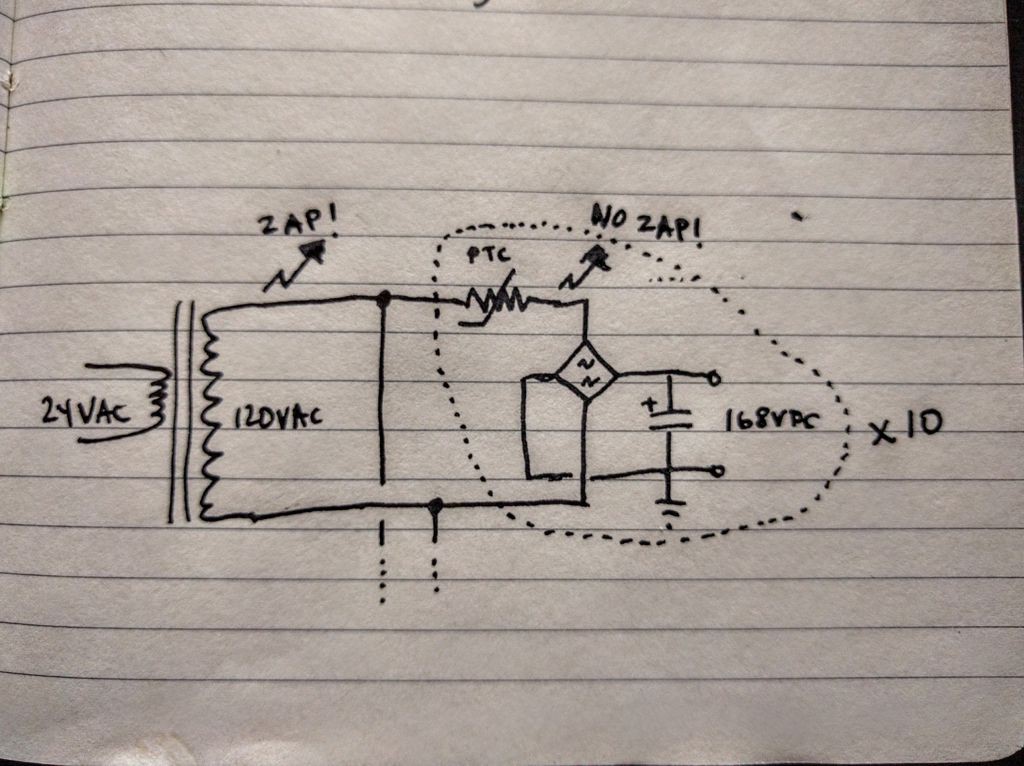
We might segment the power supply for eight tubes at a time (14.4mA). So ten rectifiers, each with its own capacitor. Touching this capacitor might hurt, but wouldn't be anything near enough to kill you. As stipulated in the previous log, if we want to drop no more than 8V in 1/120 seconds, the capacitor for 14.4mA would be 15μF. The energy of such a capacitor at 168VDC is 210mJ. A Joule is a watt-second, and 0.21W-sec is nowhere near the lethal amount.
Now, there's one tiny flaw in this plan. There's still nothing limiting the supply current if you short your 500-ohm body across one of the capacitors. You'd get 168VDC across that, which is 57W and thus lethal. We want to current-limit each segment of the supply before it hits its rectifier.
I think this can be done with a PTC resettable fuse, something like like this:
![]()
A PTC is just a resistor with a Positive Temperature Coefficient, meaning that it gets hot, and as it gets hot its resistance goes up. PTC fuses have their resistance shooting way up quickly. The specs for a PTC fuse give a hold current and a trip current, where the fuse will go off somewhere between the hold and trip current. The Amphenol YM120C15N182 PTC has a hold of 16mA and a trip of 23mA, which means we'd never hit the lethal 26mA at 168V. The PTC would blow first, hopefully within three seconds. Maddeningly, the datasheet doesn't give a time to trip, so I'd have to experiment, or find a part with similar hold and trip currents that does have a defined time to trip.
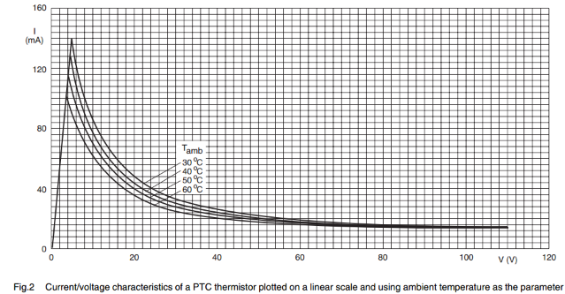
Here's what the I/V curve for a PTC looks like (from Vishay's PTC Electrical and Mechanical Properties).
So the resistance is very close to constant until the thing trips, and then the resistance shoots up.![]()
PTCs can take any amount of time to reset. Sometimes they never reset. But hey, at least you're not dead.
-
Power considerations
04/18/2016 at 18:07 • 2 commentsPower! Surely 80 Nixie tubes will require lots of power?
According to the datasheet, a digit takes a maximum of 2mA while the dot takes 0.3mA. Call that 2.3mA, assuming that all places have a digit and the dot lit. Times 80 is 184mA. At 170VDC, this is about 32W.
My plan is to provide 170VDC by rectifying wall voltage (120VAC where I am). The "120" in 120VAC is not peak-to-peak, but root mean squared, meaning that peak-to-peak voltage is 1.4x RMS voltage, or 168V, close enough.
Now, suppose I don't want to drop below 160VDC in the 1/120 seconds it takes for the rectified voltage to go from peak to peak. I = C dV/dt, and let's just approximate that by I = C ∆V/∆t. For 184mA and ∆V/∆t = 960V/s, we get C = 192μF. Also, such a capacitor needs a working voltage of at least 200V.
There are a lot of approximations here. For example, the Nixies, when on, aren't going to sink a constant current when the voltage changes. But this is close enough for good operation.
Also, let's assume 92mA flowing through each recifier diode (since each conducts for only half the cycle). I'm using the KBP206G diode bridge, which looks like it has a drop of 0.7V at 100mA. So two diode drops at 92mA (average) is 130mW, which is nothing compared to the 32W needed.
Finally, I'd like to use an AC wall-wart to power the calculator so that I don't have to touch the mains. At Digikey, I found a 24VAC adapter at 43W (Triad Magnetics WAU24-1800) which seems like it should more than power the display plus all the other electronics. Then I can just use a transformer to convert 24VAC back up to 120VAC, rectify, and I'm done.
RPN Nixie Calculator
A programmable RPN calculator using way too many Nixie tubes


 I put the initial four in at the corners, covered with a piece of cardboard, flipped the whole thing over, and soldered them in. This helps keep the tops of the tubes at the same level. Then keep going, doing four or five at a time.