jcchurch
-
All Shapes and Sizes
06/16/2016 at 04:24 • 0 commentsMechaduino works with just about any bipolar stepper motor. Here are a few that we've tried:
![]()
Banana for scale. The large NEMA 23 in front boasts 21.3 in-lbs at its rated current of 1.8 A!
-
What's next?
06/01/2016 at 20:10 • 7 commentsWe're looking at new features to add to the Mechaduino. Let us know if there are any features/applications that you would like to see! Here's a list of some of the things we're working on implementing:
-An easy to use anti-cogging calibration routine (we have a crude routine right now)
-PID auto-tune routine
-Acceleration limits in position control mode
-SPI firmware (hardware is there, just need to finish code)
We're also thinking about designing a couple shields/daughterboards. There are some hardware features that we decided not to include on the base Mechaduino since they would drive the cost up significantly and would probably be unnecessary in most applications. Shields/daughterboards would allow users to add these features when necessary. Some ideas we've had:
-High current H bridge shield (for larger motors)
-CAN interface shield
-esp8266 shield
- cable to plug into stepstick headers on ramps boards (not a shield, but still add on hardware)
Also, we're working on cleaning up the firmware. Right now it all works, and we've tried to add comments where necessary, but it's still a little messy.
-
Application Examples
05/27/2016 at 17:04 • 0 commentsHere are some demonstrations that we've been working on. Using the motor in these different applications has helped us evaluate our own design and make improvements where necessary:
Closed Loop 3D Printer:
Demonstration of a rep rap Prusa with closed loop position control.
A Mechaduino servo motor can be used as a drop in replacement for each stepper motor and stepper driver. The Mechaduino has interrupt based step/direction command handling.
Closed loop control means that external disturbances or rapid accelerations will not cause a loss in steps.
Closed loop motors run more efficiently since they only apply the required torque to track a position command. Stepper motors must apply their maximum torque all the time. This means that the closed loop motor will run much cooler and can apply much higher peak torques.Electronic Gearing/Haptics:
Implemented with analog setpoints and two motors:
M1 position -- to -- M2 setpoint
M2 position -- to -- M1 setpoint
It works! Could use some filtering to remove noise, but not bad for first attempt! Could also be implemented over serial or I2C.
Applications include synchronous motion applications, but also extend to haptic force-feedback: torque applied to one shaft is felt on the other. A pair could be used to link motion of a joystick to a robotic arm, allowing the operator to "feel" when obstacles are hit. Could be used for bi-directional tele-operation of equipment. Imagine transmitting force and motions through the tactile equivalent of skype!Robotic Arm:
A quick demo of a work-in-progress robot arm that uses a Mechaduino closed loop servo motor. Arm will eventually have 5 DOF.
Toilet Paper Dispenser:
This is primarily a demo of the Mechaduino servo motor. This novel bathroom appliance is a good way to show off the mult-mode capabilities (specifically force sensing, position control, and profile tracking) of the motor.
This application is totally self contained. Everything including the led indicators is controlled directly from the Mechaduino. It took only about 15 minutes to write the code for this custom Mechaduino application.
In addition to being a Mechaduino demo, we've realized that this little device could actually be a useful assistive technology since it only requires one hand to operate.Record Player:
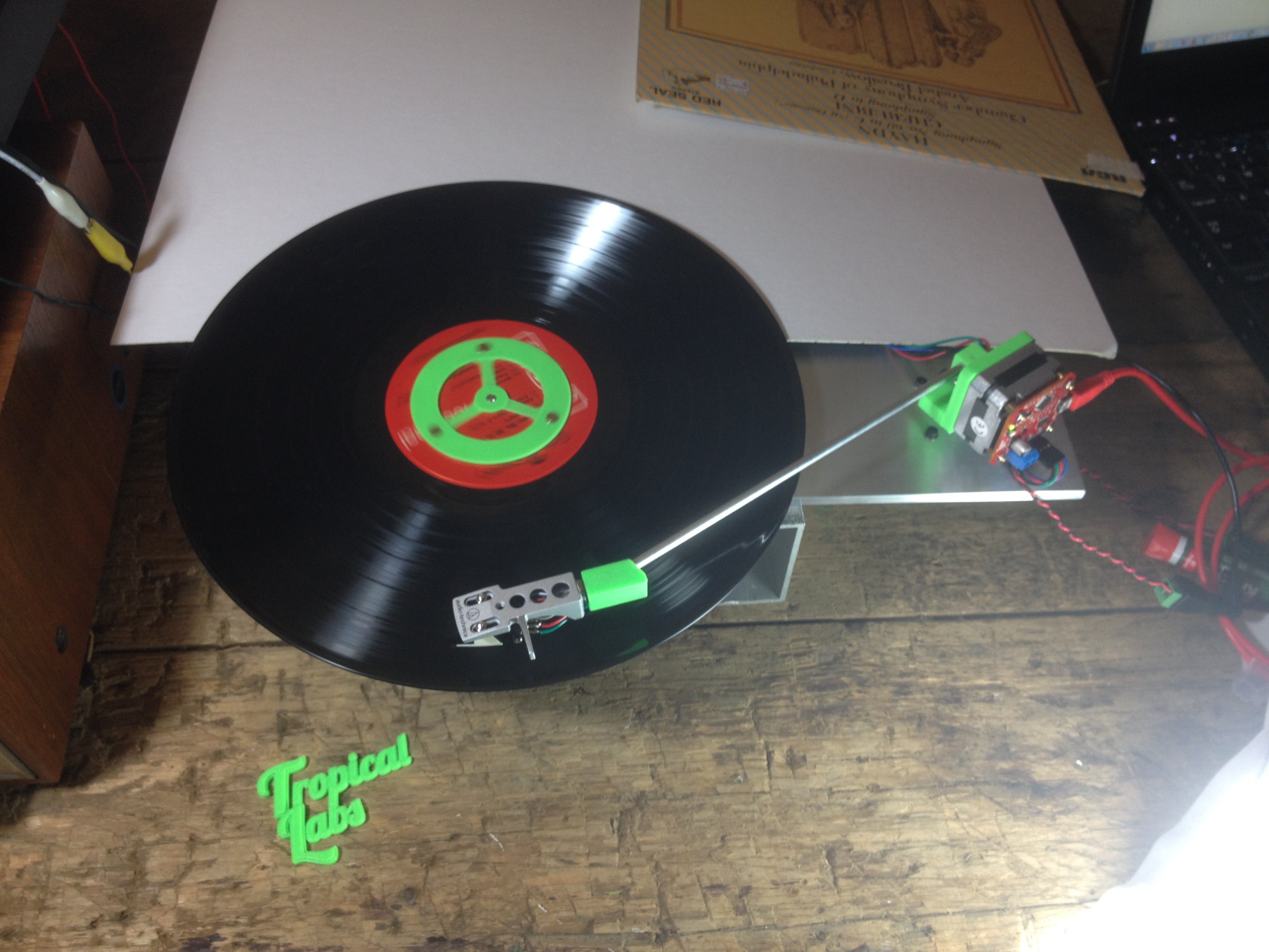
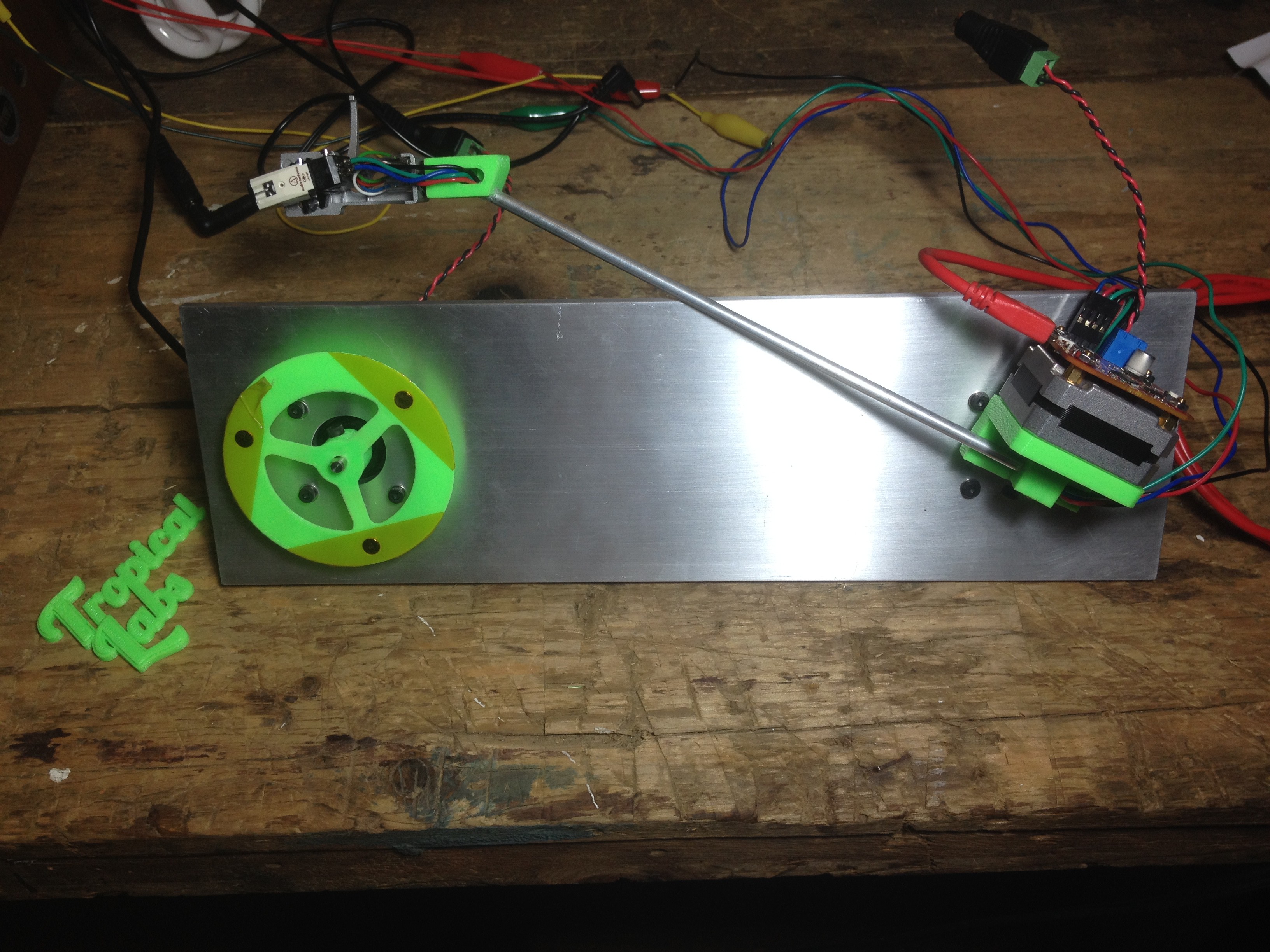
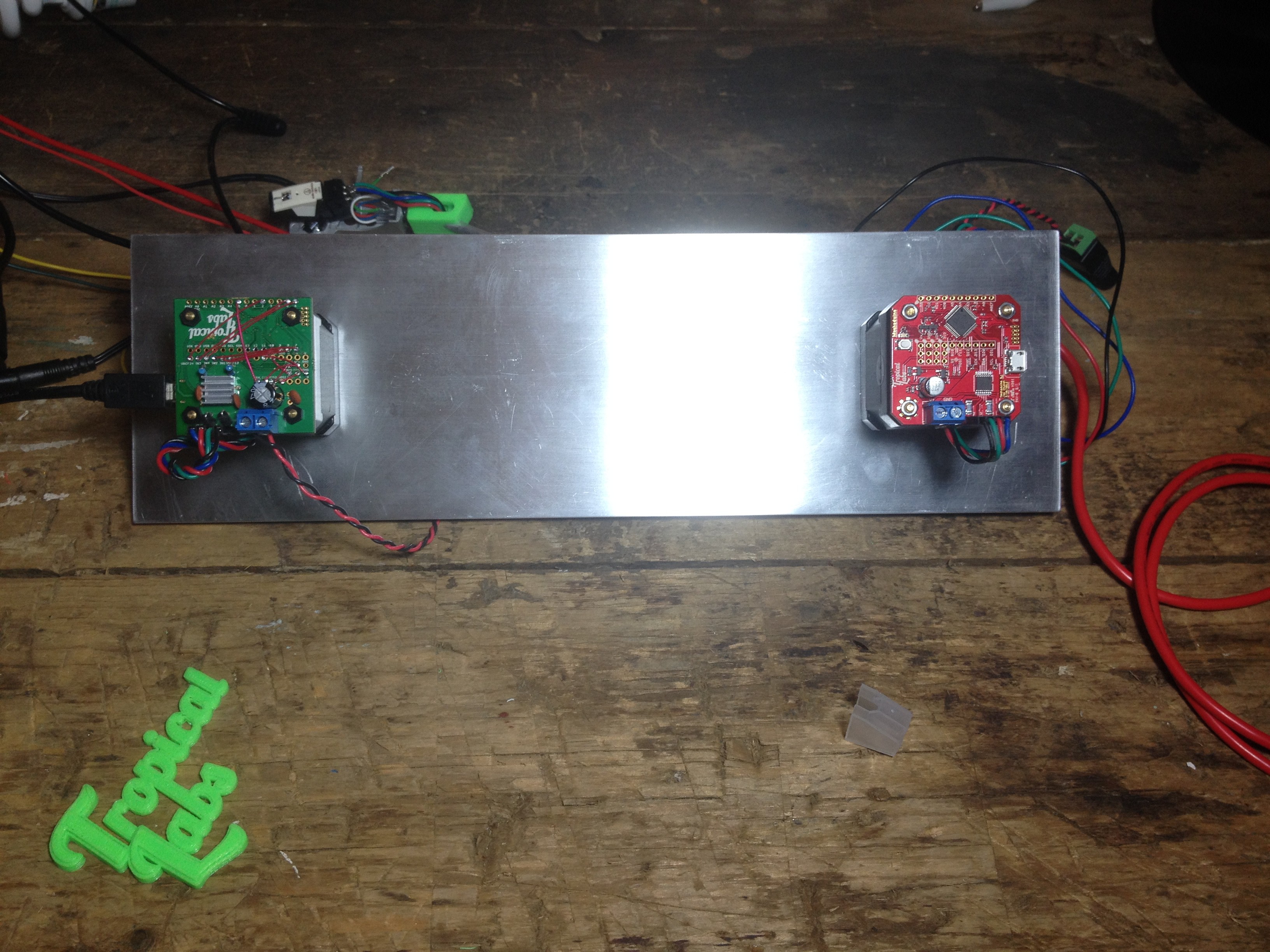
This is a bit of a teaser... the record player is still a work in progress, but we're very excited about it.
The idea is that instead of using a gimbal to allow the tone arm to move, we will have two Mechaduinos control the needle movement. This will open up the door to all kinds of interesting capabilities. Using gravity compensation, the record player could be hung on a wall and play the record vertically. Since we have full control of the needle movement, we've designed the tone arm to be able to flip backwards and around in order to play the back side of the record. Yes. This record player has auto reverse.
And, of course, the record itself is spun by a Mechaduino in closed loop velocity mode.
![]()
![]()
![]()
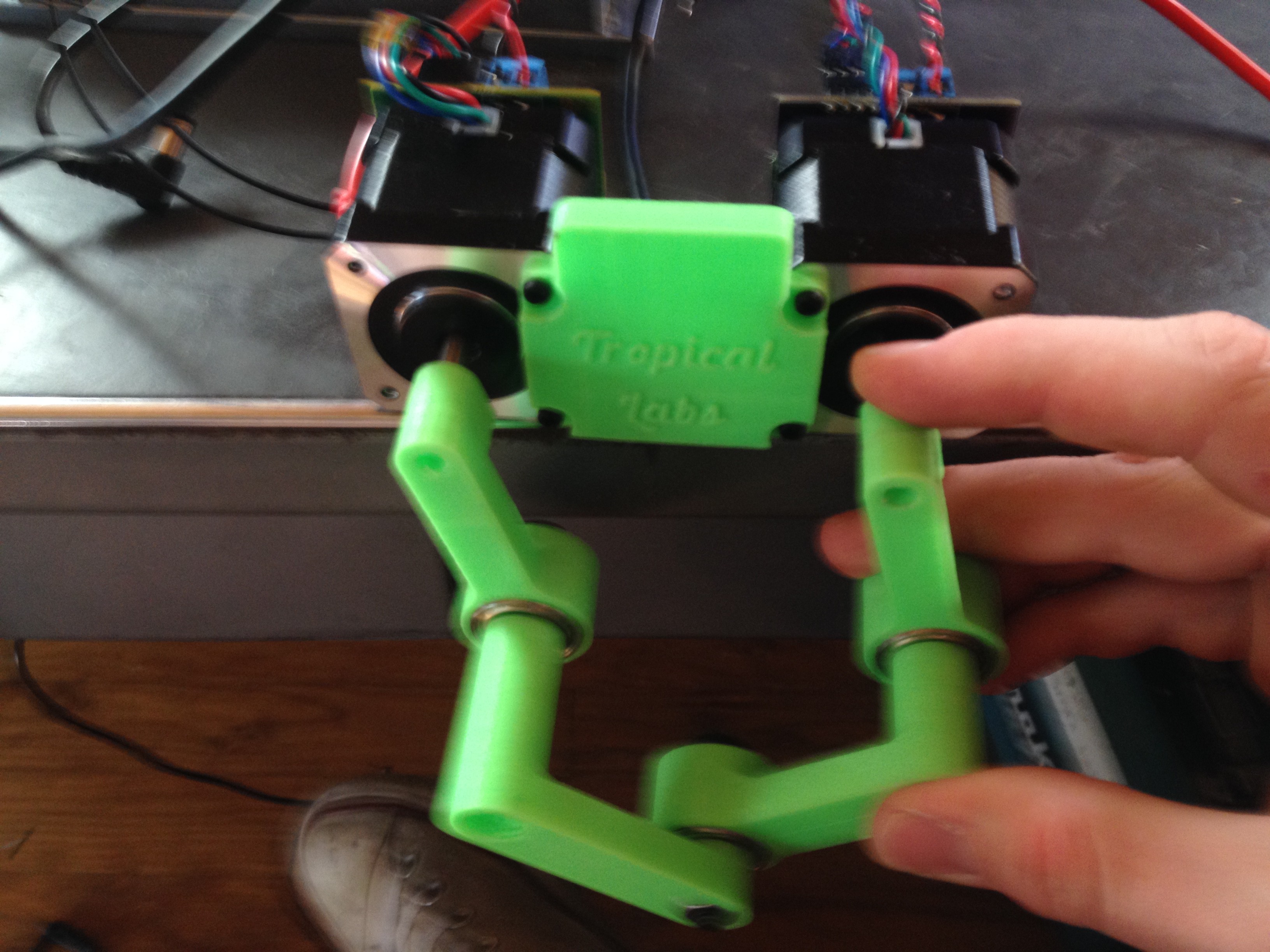
5-Bar Scara Robot:
Another teaser. Parallel robots often have complicated kinematics: You have to do a lot of math to go from motor positions to end-effector position and back. With this little 2 DOF positioner, we'd like to show off a "training" mode of the Mechaduino. Rather than performing motion planning and solving forward and inverse kinematics, a user will be able to move the arm through a desired trajectory, training it.
![]()
-
Mechaduino 0.1
05/24/2016 at 07:45 • 0 commentsNew prototypes just arrived!
This version features hardwired connections to the motor driver and encoder (no more jumpers!), fewer through-hole components (only connectors), 5V compatible level shifters on D0 and D1, and a more thoughtful board layout. The new boards are slightly smaller, and do not overhang the edge of a NEMA 17 motor. We also arranged our power connections so that a 3 terminal 5V regulator (the classic 7805 or a modern switching equivalent), could be installed for single supply operation.
All the latest design files are on github!
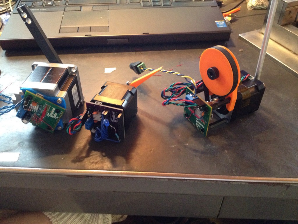
![]() Here's a photo of the older prototype boards (Mechaduino 0.0) wired up to a few different stepper motors including a NEMA 23:
Here's a photo of the older prototype boards (Mechaduino 0.0) wired up to a few different stepper motors including a NEMA 23:![]()
-
Calibration Routine
05/24/2016 at 07:14 • 0 commentsHere's a video demonstrating the magnetic encoder calibration routine.
There are two reasons for this calibration routine:
The first reason is to correct for the magnetic encoder's linearity. The second reason is to relate encoder position to motor phase angle. More on that below.
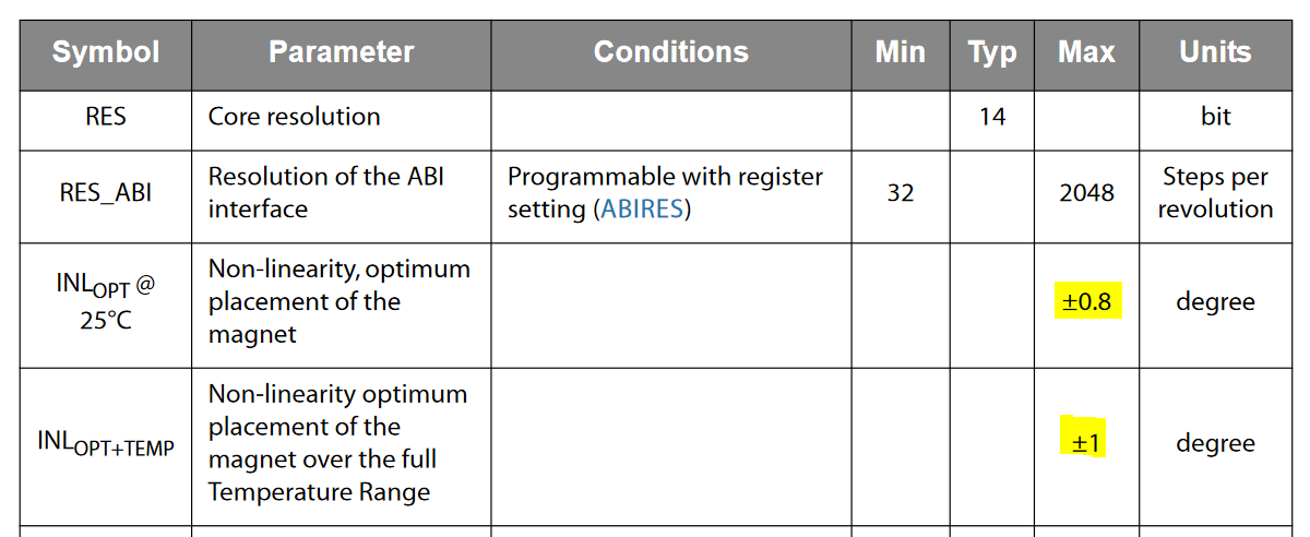
The AS5047 claims to have a resolution of 14 bits or about 0.02 degrees. This is true... but it is only accurate out of the box to about +/- 1 degree. Not so good. From the datasheet:
![]()
It turns out that this non linearity manifests itself as a very repeatable sinusoidal error with a period of 180 degrees. (Observed through experimentation... graph coming shortly).
Our calibration routine compensates for this by stepping through well known positions and recording the encoder count. Stepper motor full steps are a fairly accurate position reference. Most manufacturers guarantee accuracy to at least better than 5% (5% of 1.8 degree step is 0.09 degree, worst case).
We now know the encoder counts at reference positions and can interpolate between each step and create a lookup table.
This technique has the advantage that it automatically relates encoder angle to motor phase angle, so they can never be misaligned!
I'll post some more details and data that I've collected here shortly... I'm on the road, away from my lab computer.
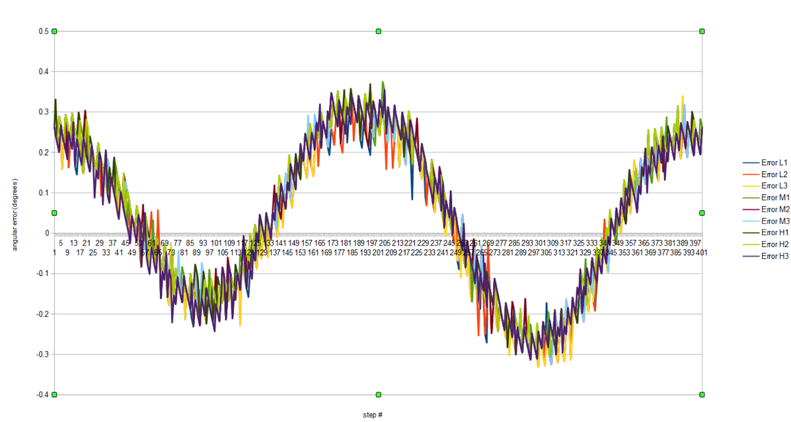
Here is a plot that shows the angular error of a AS5145 sensor (one revolution). This is an old plot from our first prototype. The discretization noise is much worse here since it is only a 12 bit sensor. You can clearly see that the sinusoidal error is very repeatable though. I'll upload the most current data asap.
-
First Prototype
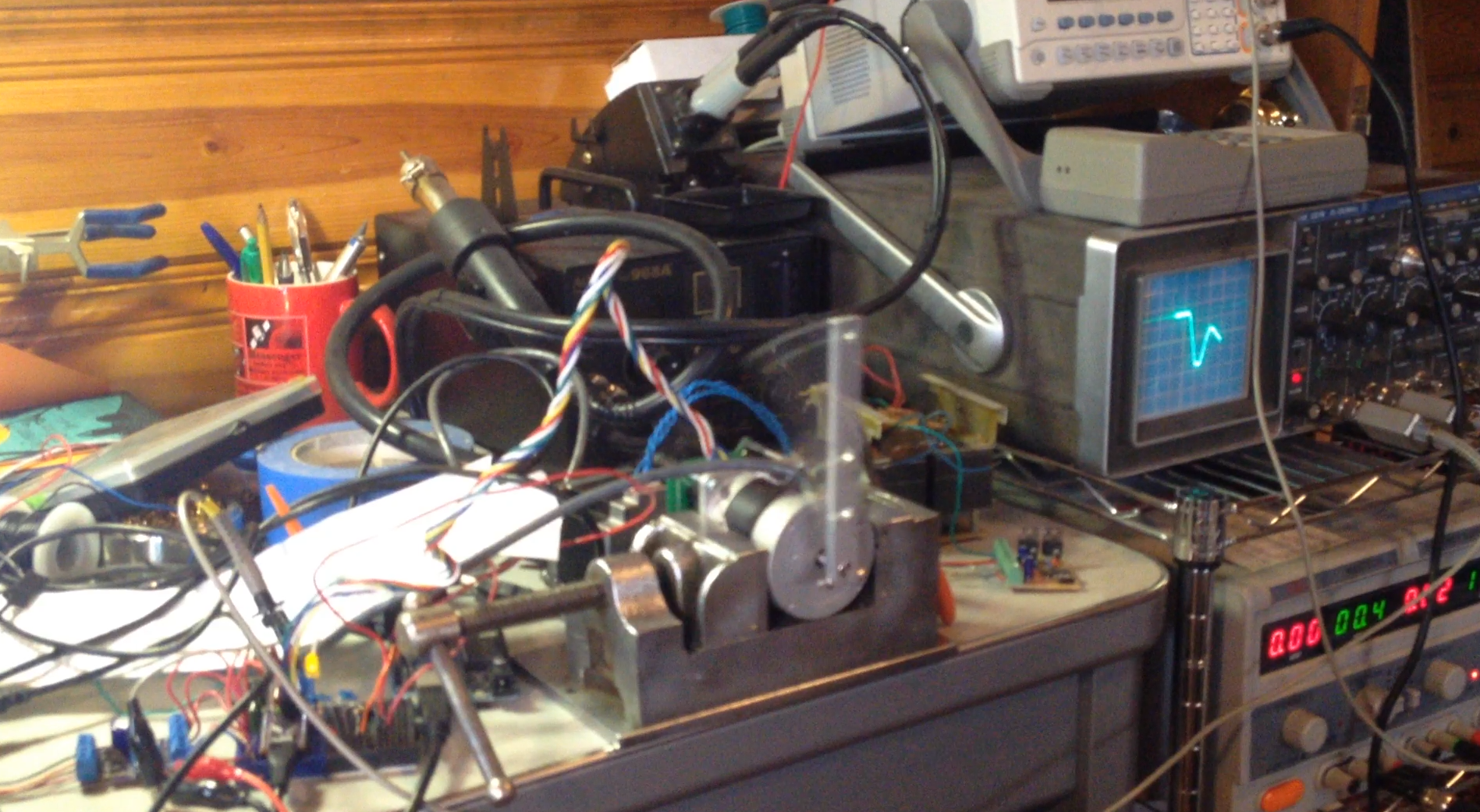
05/02/2016 at 05:11 • 0 comments![]()
The first breadboard-level prototype. A4954, AS5047, and SAMD21 breakout boards controlling a NEMA 23 stepper motor (closed loop position control).
This was our proof of concept. We wanted to see if it would be possible to control a stepper motor like a closed loop BDC servo motor at all.
At first, we tried to use an Arduino Uno compatible Atmega328, but found that it was a little bit too slow to run the control and commutation algorithms. We also began to run out of memory, so we moved over to the bigger, faster ARM M0+ SAMD21 (Arduino Zero compatible). We looked at a number of other microcontrollers, but in the end we decided that we really wanted to maintain Arduino compatibility to keep the control algorithms as accessible as possible to users.
We experimented with a couple different magnetic encoders. We were hoping to use the "16 bit" AEAT-6600-T16. Unfortunately, if you read the datasheet very carefully, you find that the resolution is only accurate to 16 bits in "slow mode"... which happened to be way too slow for closed loop control. We experimented with the hardware, and we were able to confirm that in "fast mode" this encoder is only accurate to about 10 bits... which isn't that great.
AMS has a dozen or so different magnetic encoders, and we experimented with a few. They're all pretty similar, but offer different output configurations, resolutions, etc. In the end we chose their 14 bit AS5047 with SPI output.
As I've mentioned elsewhere, ALL of these magnetic encoders suffer from non-linearities on the order of a degree or two... which is totally unusable out of the box for our application. Consider that these stepper motors have step angles of 1.8 degrees. If our encoders can only resolve angle to within two degrees, we can't even tell which step we're on, let alone commutate sub-step! At this stage we had to see if it would be possible to develop a calibration routine. I'll get into the details of that in the next build log, but long story short, we got them to work!
We put together a custom breakout board for the A4954, and were pleased with its performance. This chip worked out great since it has two chopper controlled H bridges in one package... perfect for bipolar stepper motors, and low cost/part count for us!
In the end we were very encouraged by the performance of this crude setup. We achieved our goal of closed loop position control. The next step was to put everything on a custom PCB, and clean up the control architecture.
-
Open Source License
04/25/2016 at 06:40 • 0 commentsThis isn't a real build log, but my description rolled over past the break, and I think this info should be visible on the main page:
All Mechaduino related materials are released under the
Creative Commons Attribution Share-Alike 4.0 License
https://creativecommons.org/licenses/by-sa/4.0/
Real build logs will be coming shortly! Please leave a comment if there are any particular aspects of the design you are interested in me covering.
Mechaduino
Mechaduino is an affordable, open-source, industrial servo motor. Position, torque, velocity, and custom modes. Arduino compatible.

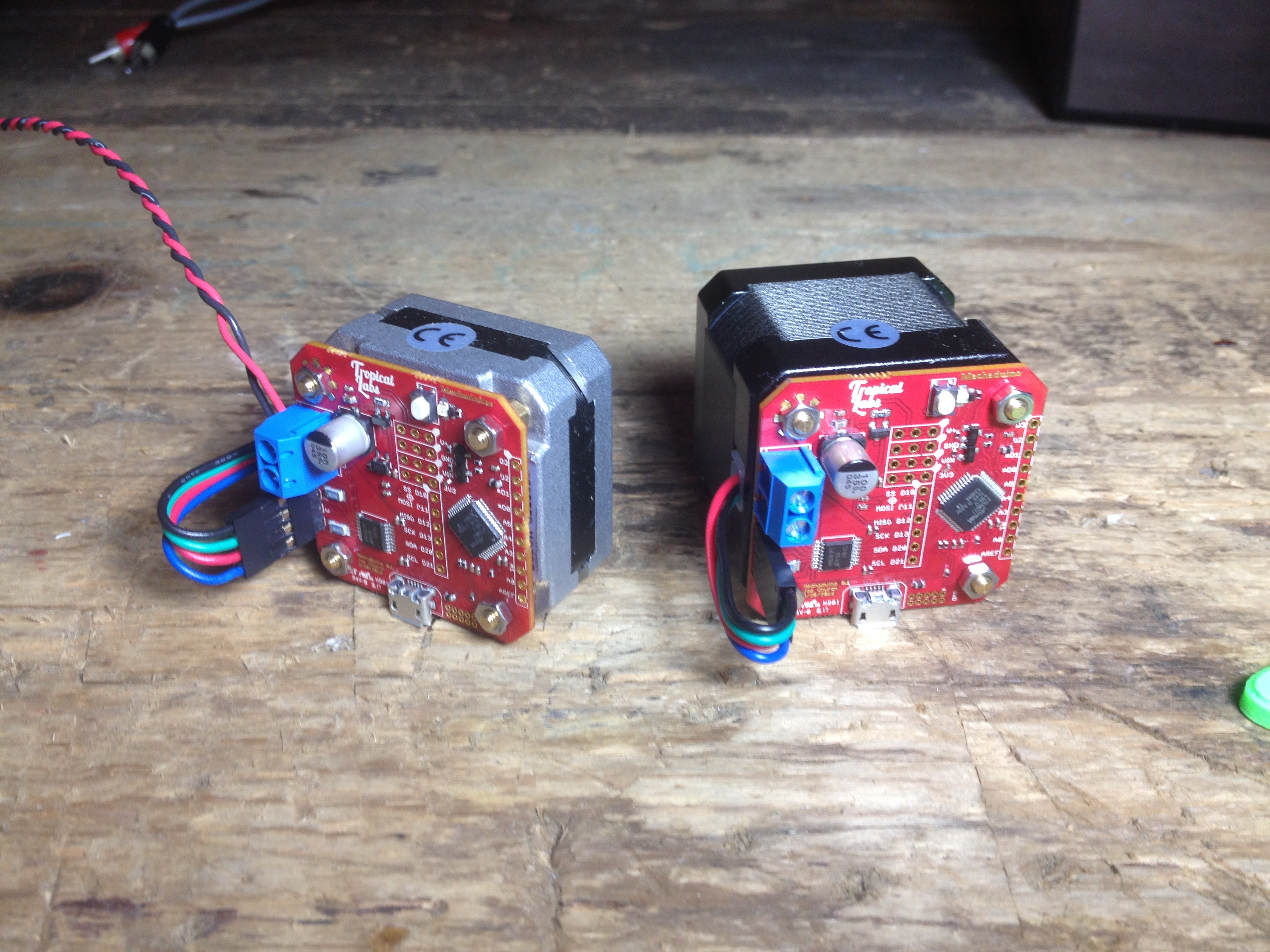 Here's a photo of the older prototype boards (Mechaduino 0.0) wired up to a few different stepper motors including a NEMA 23: