 frankstripod
Capacitive Touch Mouse and Keyboard Sharing:
I put the description first, then pictures and how I hacked it later.
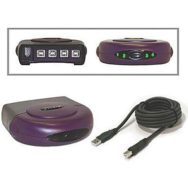
The Teensy switches and manages a four port USB switch with four LED's and four touch sensor buttons
Synergy: Please visit and donate to synergy-project.org.
First I would like to explain my love and addiction for a program called Synergy. It shares a keyboard and mouse between multiple computers. One computer with a keyboard and mouse is set as a Synergy server, then other computers are added as clients and communicate over a local network. I love that its Open Source, multiplatform, and has a quick smooth transition from one screen to another.
Synergy dislikes:
- Its network dependent so any computer or router with a hint of connection problems fails.
- All client keystrokes like passwords and account numbers go through the local network, although there is an option for encryption.
- Setup can be complicated with mixed platforms.
- It can not be used on screens where the client is disabled. For example; BIOS setup, Windows user account control, live CD's, some network passwords and user logins.
How its hacked:
I purchased this four port USB switch years ago to avoid the aggravation of swapping USB plugs every time Synergy disconnected.
 I hacked
the USB switch into a hardware solution by having the Teensy
Microcontroller do the switching for me.
I hacked
the USB switch into a hardware solution by having the Teensy
Microcontroller do the switching for me.
It originally worked by pressing the only switch, which increments the port number by one, and back lights the port number LED.
Inside:
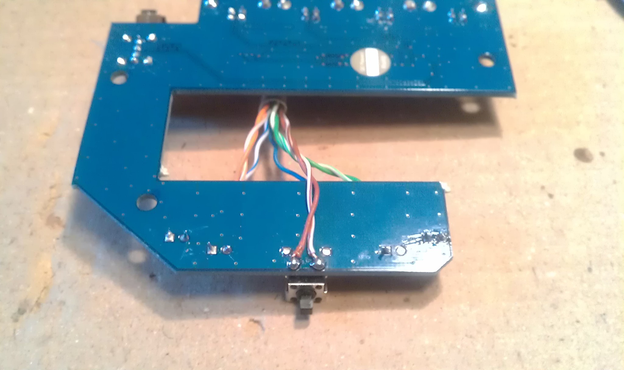
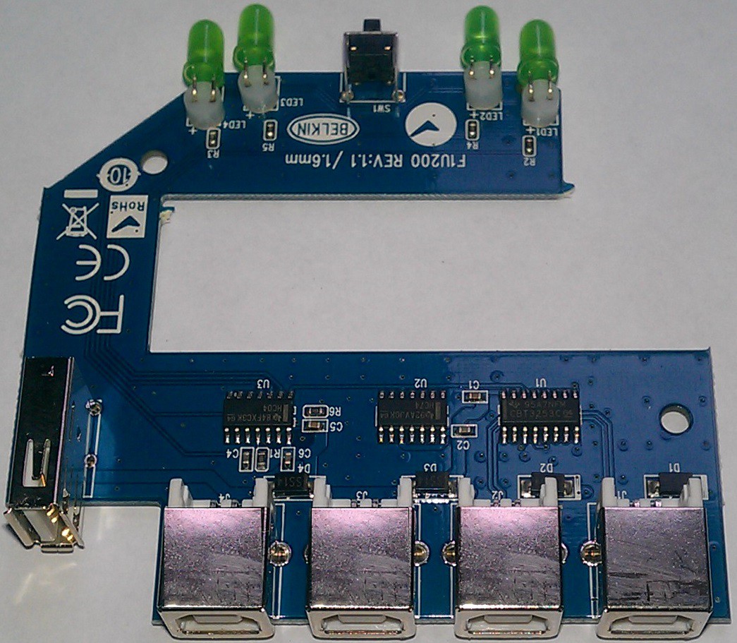 If you cut the board in two, I would want the lower half behind the desk, out of sight with all the wires. The upper half looks like it needs a hacking onto the top of my trackball!
Desoldered the LED's.
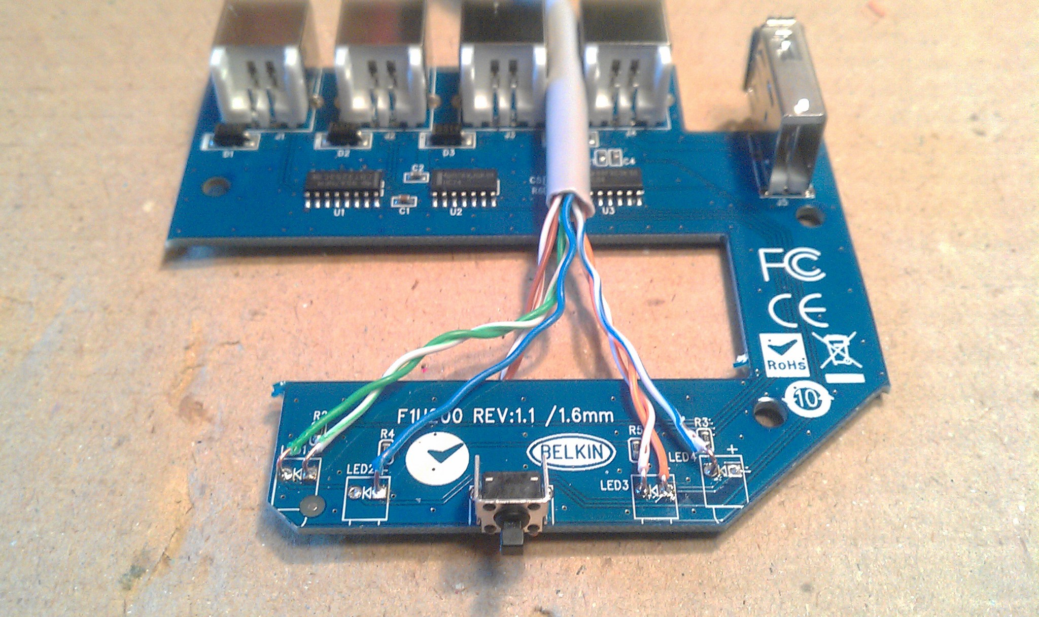 I tested the circuit with a multimeter and the wiring was confusing at first because the left pair of LED's connect anodes to ground, and the right pair connect cathodes to the same ground. To keep it simple, and to utilize the built in resistors...
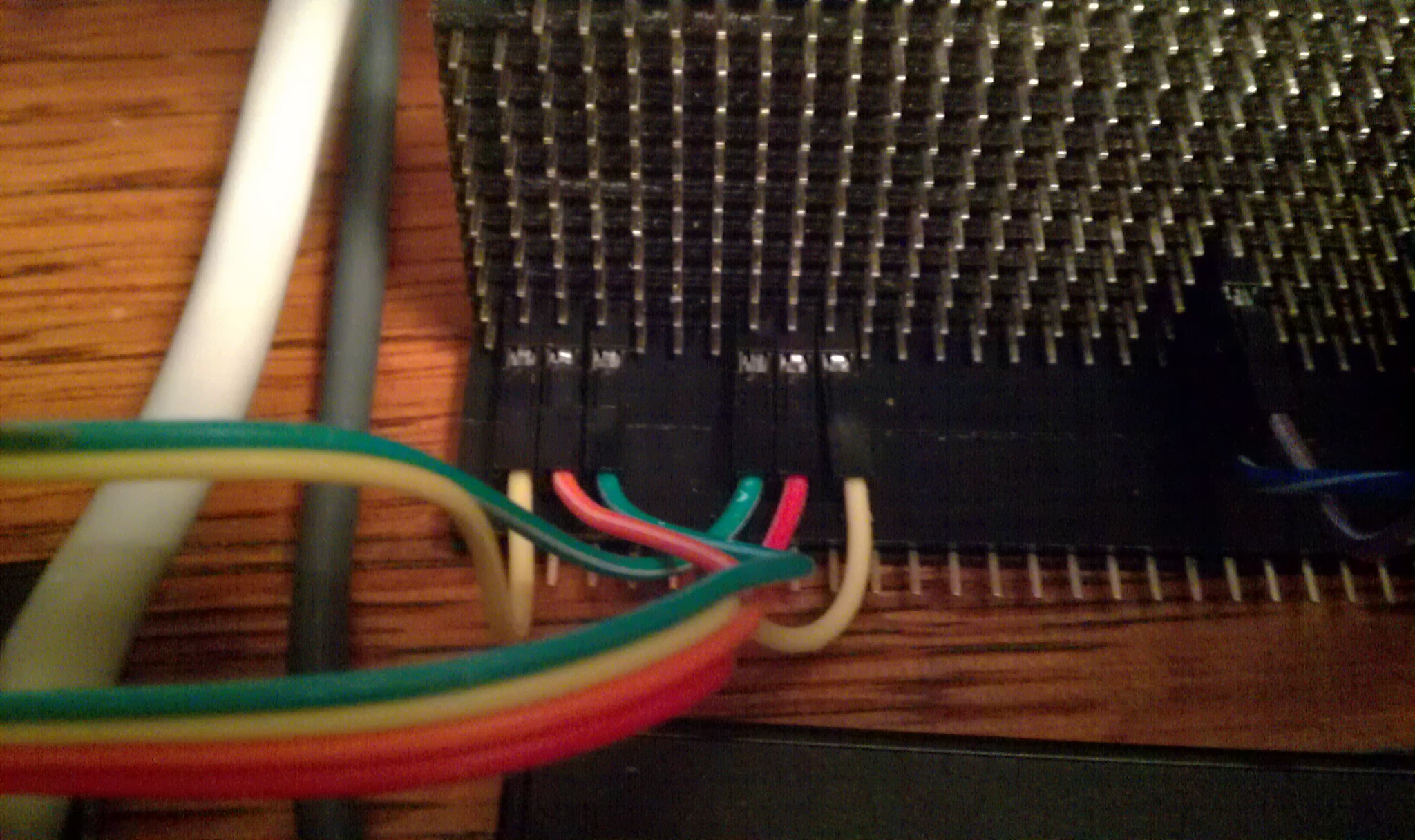
 ... I kept the circuit the same through the CAT-5 wires:
Each pair of LED's gets three wires: LED#1+, LED#2+, common pair ground.
Plus two to short the switch underneath.
 Homemade two pin female jumpers made from two pin headers.
Common ground wires matched in pairs.
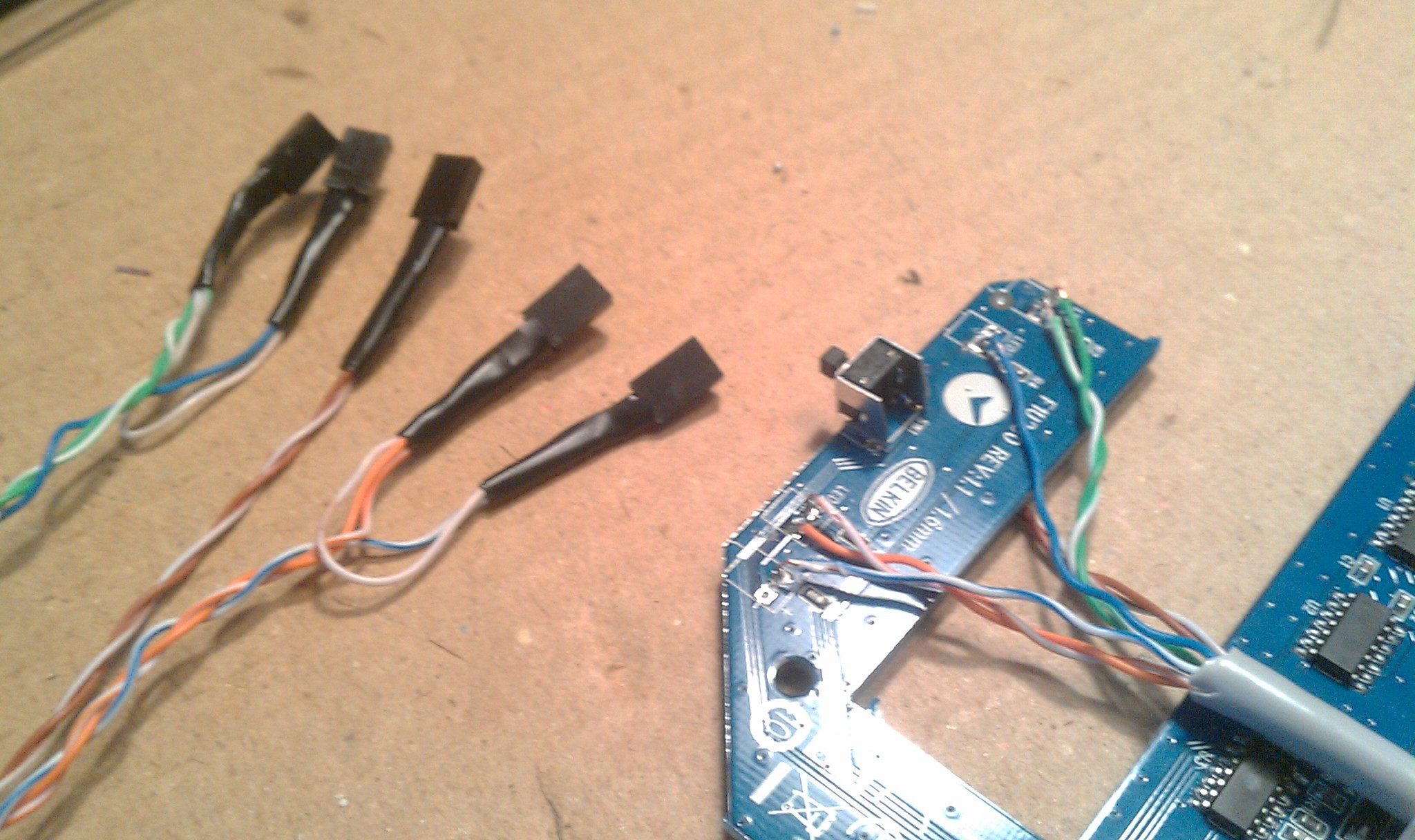 Back in its shell. Cable runs through missing LED hole, strain relieved by a cable tie on the inside.
A USB switches' worst nightmare...
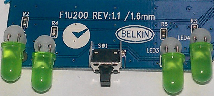
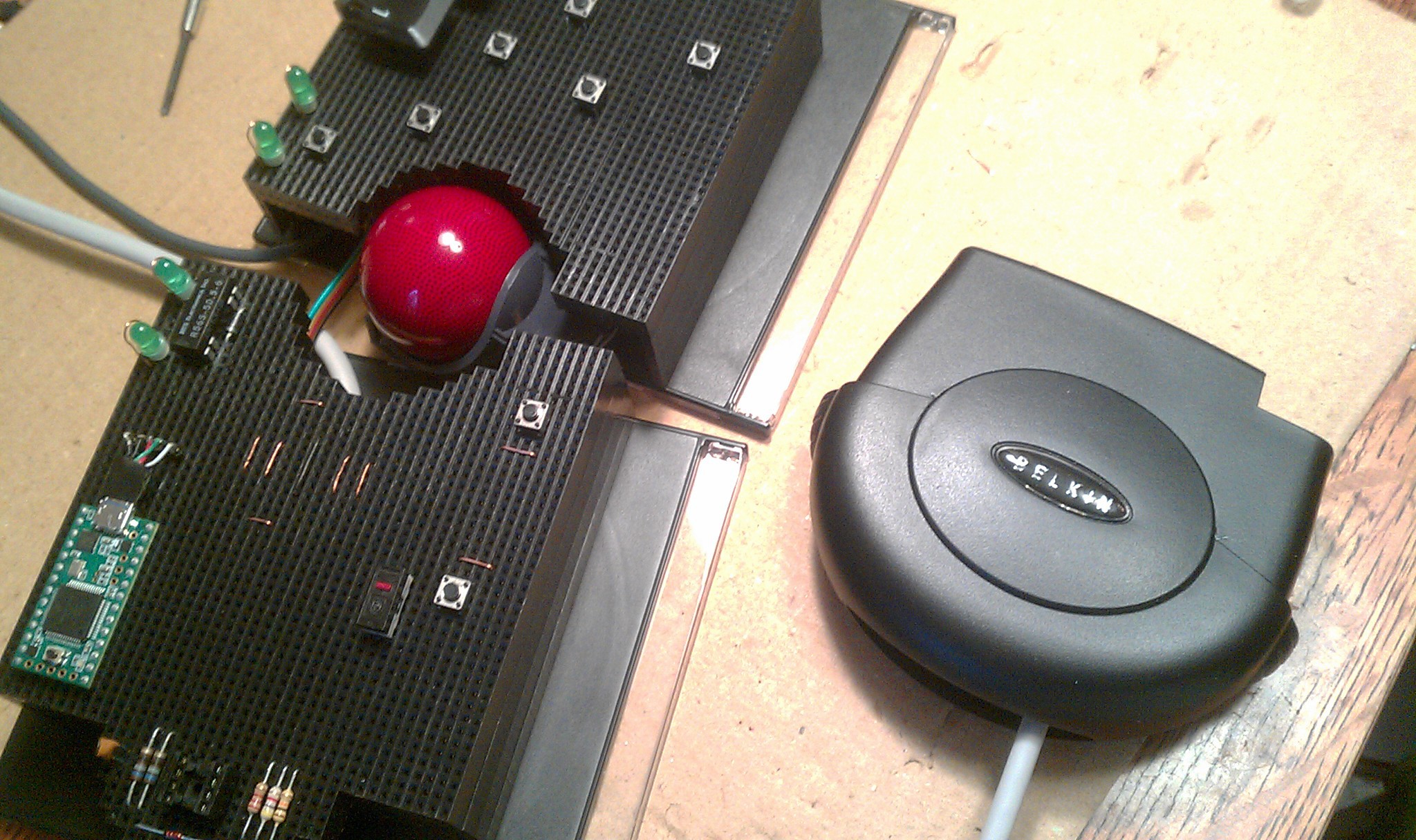 ... and kept alive to see its own working LED's amputated and transplanted on my track ball.
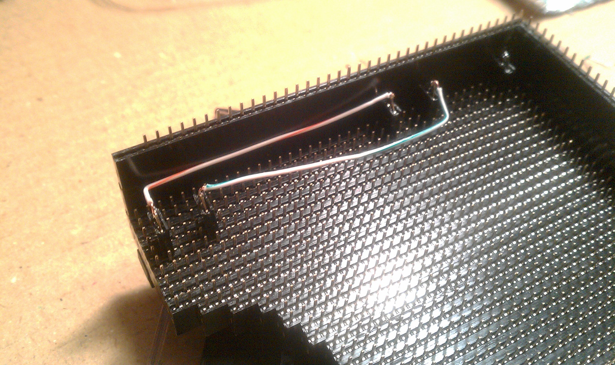
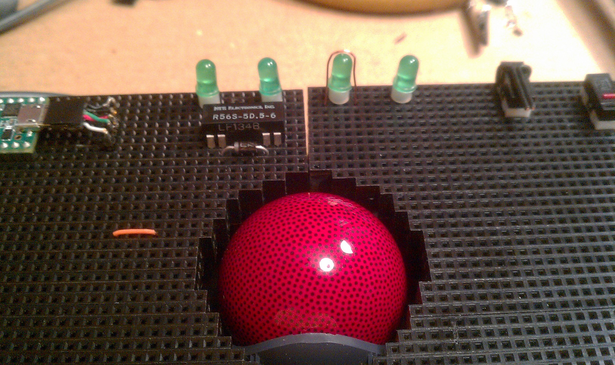 The wire on the third LED is a hacked experiment for touch sensors on LED's.
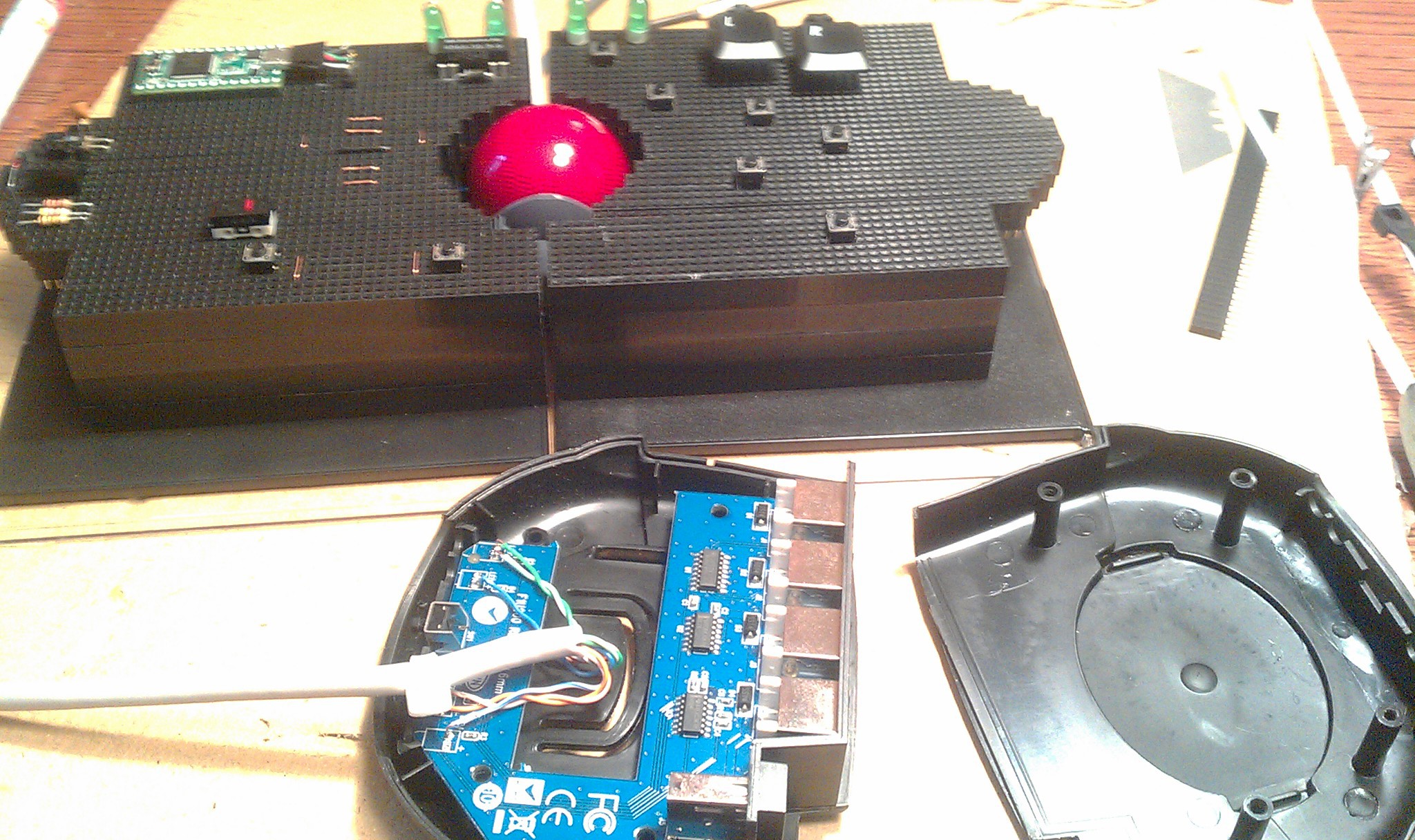
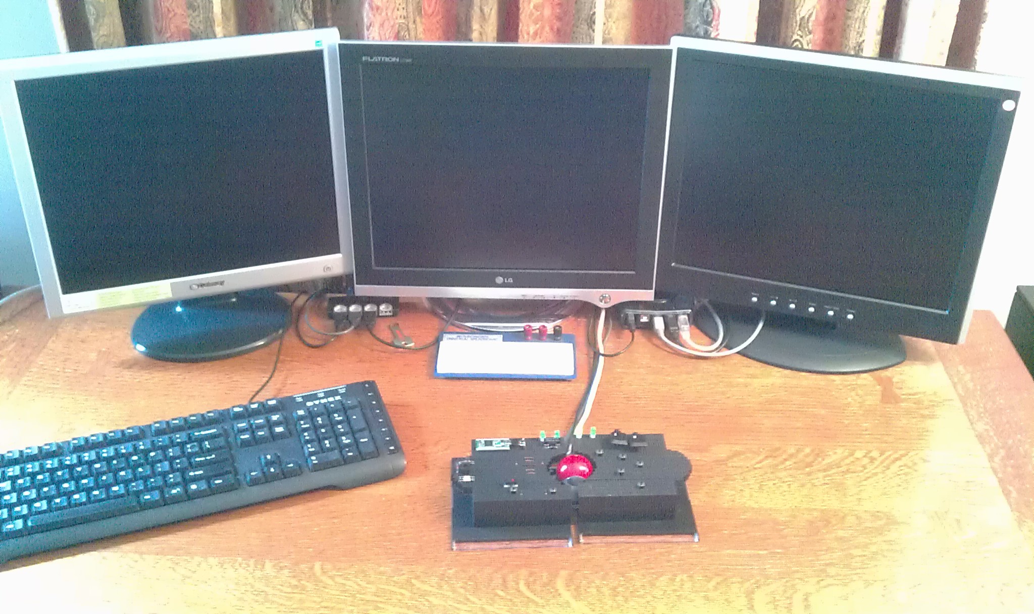
Desktop integration on three computers:
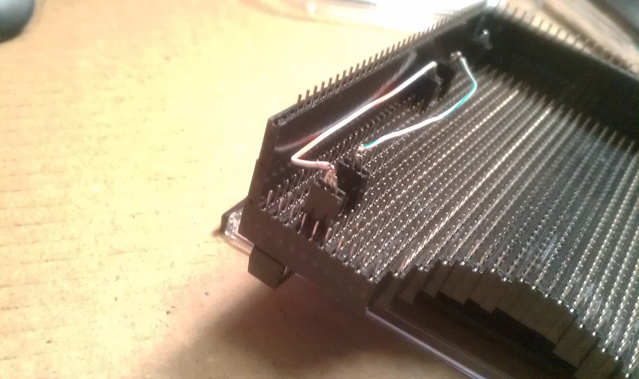
Cable restrained to the base. The more flexible wire female jumper wires connect to the solid wire, then taped.
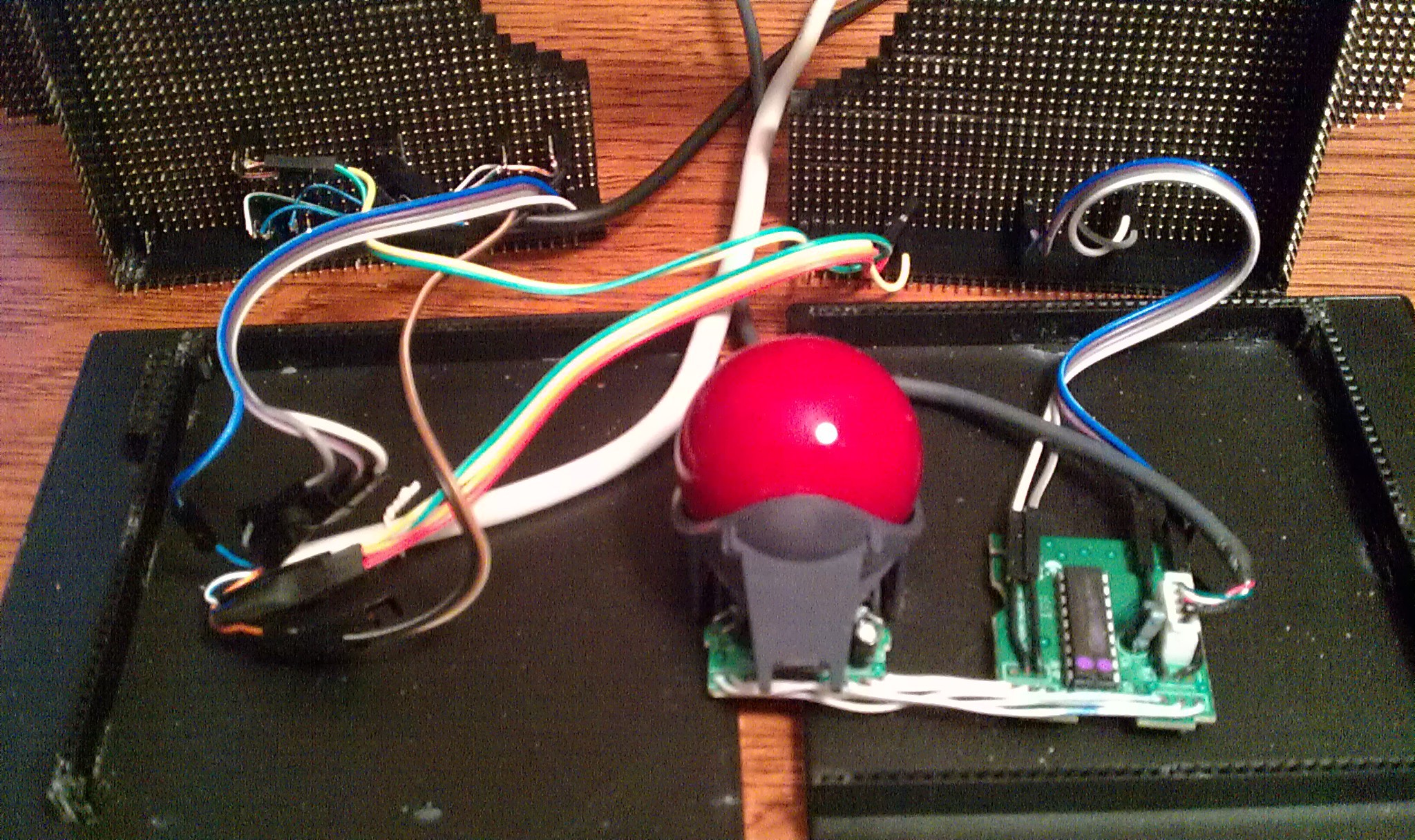 Then plugged directly underneath the transplanted LED's
 The third jumpers connect under the touch sensor wires.
Connecting the Teensy:
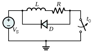
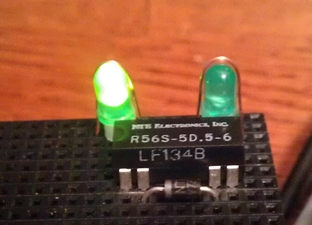 I used an NTE R56S-5D.5-6 reed relay: (5v, 3.8v min), and a "flyback diode." The relay does not have a built in diode. (the "R56S-5D.5-6D does; that first "D" is tricky. NTE_R56_57specs.pdf )
Thanks to the PJRC forums for the information on the flyback diode saving the Teensy from sure death from the relays coil. Next time I will get the ones Paul recommended;
http://forum.pjrc.com/threads/23693-Baisc-Teensy-2-is-the-switch?highlight=9007-05-01
http://www.digikey.com/product-detail/en/9007-05-01/306-1063-ND/301697
The NTE116 (1N4004) diode and the relay were in stock at my small local electronics store.
Jumpers made from two pin female headers and solid strand wire:
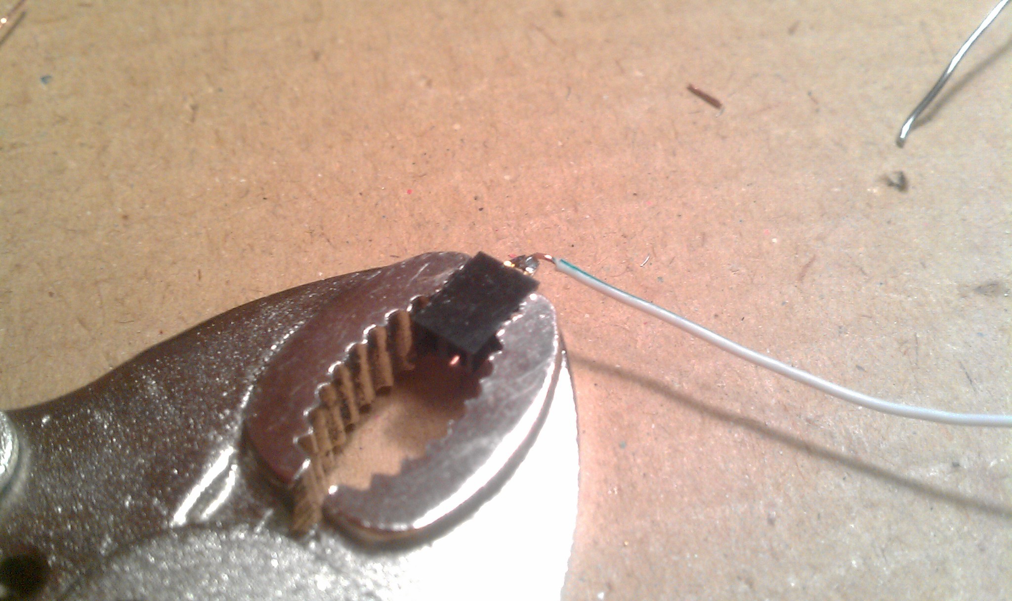 The two header sockets have the wire insert 3mm pin fix. The two male pins are bent together into a two pin jumper, and then soldered to the wire. This connects the relay to the diode in parallel. See relay pins pictured above.
 Two pin jumpers relay to diode:
Two pin jumpers on the Teensy side make for easy access breakout sockets on top.
The code for the Teensy is simple:
See which LED is being touched, figure out how many steps from the current port to the desired one with some simple math, then send that many long delay pulses to the relay. The coed is below and needs to be cleaned up. I was trying to blindly integrate variable names. The delays were easy to figure out by "higher/lower" testing for speed and consistency.
I triple checked the connections before connecting the Teensy. It turns out the relay sends an unknown (to me) signal to the USB switch moving it backwards (decreasing); so I just reversed the formulas in the code to work backwards.
Wish List:
Making an Open Hardware trackball with optical encoders, controlled by a microcontroller, that traces mouse movements to calculate each computers mouse pointer position (without drivers). That will allow for screen edge detection and gestures for smoother faster screen transitions, eliminating the need for the touch sensors.
//
//
/* Mouse Controler Project 2014 @ hackaday.io by frankstripod via Teensy 3.1
*/
// Touch USB switch setup:
const int u = 4; // Number of USB touch sensors used
int upin[u]={0,1,22,23};
int ubase[u];
int usb[u];
int unow=1;
int utouch = 1;
int relay = 0;
int relaypin = 3;
// Touch sensor adjustments:
int sensitivity = 130;
int touchDelay = 100;
int Delay = 100;
int c; // Generic counter
int led = 13; // Blink conformation
void setup() {
Serial.begin(38400);
for (c=0; c<u; c++) {
ubase[c]=touchRead(upin[c]); // Baseline calibration
}
pinMode(led, OUTPUT);
pinMode(relaypin, OUTPUT);
}
void loop() {
// Read the sensors
utouch = 0;
for (c=0; c<u; c++) {
usb[c] = touchRead(upin[c]);
if (usb[c]-ubase[c] > sensitivity) {
utouch = c+1;
}
}
// Skip the rest if nothing is touched
// Figure how many steps
if (utouch) {
relay = 0;
if (utouch > unow) {
relay = 4 - (utouch - unow);
}
if (utouch < unow) {
relay = unow - utouch;
}
unow = utouch;
// Pulse relay that many times
for (c=0; c<relay; c++) {
digitalWrite(relaypin, HIGH); // increment +1
delay(10);
digitalWrite(relaypin, LOW);
digitalWrite(led, HIGH);
delay(100);
digitalWrite(led, LOW);
}
}
}
Discussions
Become a Hackaday.io Member
Create an account to leave a comment. Already have an account? Log In.