 kittan
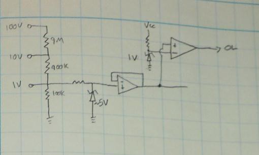
Schematic for the input divider. The idea is to allow a range of input voltages but each input is divided down to a 1V scale. The zener protects the op-amp buffer input in case you grossly overvolt one of the inputs. A 1V comparator is tied to the output, which will trip an Out-of-Range flag if the input voltage exceeds measurable values. The output from the buffer op-amp is piped into the decade legs for measurement.
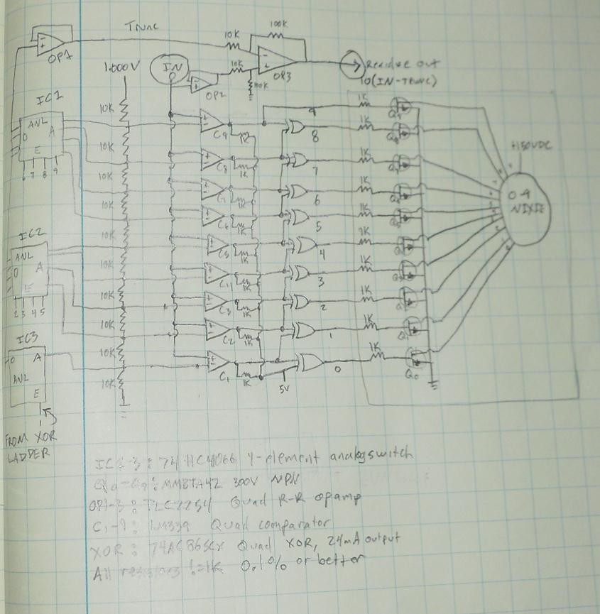
Here's a rough schematic for a single ladder leg and nixie driver. A precision 1.000V is divided by 0.1% resistors into what should be just almost exacly 0.1V increments. The input voltage will trip comparators ascending. The XOR gates take advantage of the fact that if a comparator is tripped, then by definition all comparators below it are tripped; this allows them to selectively zero out every comparator output except the topmost tripped comparator, in effect isolating the truncated decade range of the input signal (so if we input 0.865V, all comparators from '8' down will be tripped, but only XOR output '8' will read HIGH). That gate output can directly feed an NPN cathode drive transistor on the Nixie tube, illuminating one filament at a time corresponding to the decade's measured value (in our example, the '8' will be lit).
The XOR outputs are also fed into a stack of analog switches tied to the resistor ladder, each switch passing a particular voltage value from the ladder. Since only one XOR at a time is HIGH, only one value at a time is passed, corresponding to the decade measurement. The voltage passed I refer to as TRUNC as it's the input voltage truncated to one digit measurement (0.865V becomes 0.8V). This TRUNC value is fed into a difference amplifier with a gain of 10, subtracting it from the given input voltage. The output then is 10*(IN-TRUNC), which in our example would be equal to 10*(0.865-0.8)=0.65V; which corresponds to ten times the unmeasured residual voltage from our input. If that residue is piped into a second identical ladder stage, its display will read '6' and output 0.5V as its residue. The third stage will take in the 0.5V residue and output a '5' on its tube.
There are cascading error issues with this, as the accuracy of both local and downstream measurements are dependent entirely on the precision of the reference voltage and ladder divider. All downstream measurements are dependend on the ladder precision, loss in the switches and accuracy of subtraction and gain in the residue amplifier. I'll probably have to alter the residue amplifier design (instrumentation amplifier maybe) to take bias currents more into account as first-stage inaccuracies will large effect on third- and fourth-stage measurements.
Additionally the display readout will change in near-realtime (propagation delay of the entire system will slow this down from 'instantaneous' to 'near-instantaneous') so I'll have to use a switched sample-and-hold circuit on the input that updates the ladders every one or one-half second.
What is likely to happen is building the nixie drivers and tubes on a separate board, into which the divider boards connect like a backplane setup. That'll make building the ladder boards separately easier and still have an efficient unified display board. Common signals (like the 1V precision reference, 5V and GND) can be fanned to each board from there or through a common cabling header of some kind.
Discussions
Become a Hackaday.io Member
Create an account to leave a comment. Already have an account? Log In.