 mulcmu
Before finishing the dry wall in my garage, I pulled some speaker wire to connect a pair of ceiling speakers in the garage to the receiver in the family room. Having some degree of foresight, I also pulled some thermostat wire to a wall plate in the garage. Running back and forth between the garage and living room to adjust the volume would get old real quick. Initially I was planning on adding an IR repeater to control the receiver from the garage. While looking into the commercial IR repeater interface, I stumbled upon a DB9 RS232 connector on the back of the receiver. This connector allowed for control of and feedback from the receiver, plus a great opportunity for a microcontroller project. A set of built in controls using this serial connector had two big advantages of the IR repeater: no remote to lose or break in the garage and bi-directional communication from the receiver for feedback.
I could not locate a manual for my Denon AVR-2805 serial connection but the manual for the serial protocol for model 3805 was available. First step was to hook up the laptop to the receiver and test it with a USB serial adapter. The commands and feedback worked mostly as described in the manual. The terminal text was saved and annotated a bit to help with the software development later.
I had run two 5-wire thermostat cables between the wall plate in the living room and the one in the garage. On the garage side of things, I think I could have just used buttons and leds with the electronic portion located in a project box behind the TV. I was looking for a cleaner solution than an extra box behind the TV and thermostat wire running out from the living room wall plate. I had some S-Video keystone inserts that would support 4 wires: Power, Common, RX, & TX. This would allow the whole project to be contained behind the wall switch.
Next decision was how to power the in wall unit. Putting batteries in the wall easiest option and likely the most efficient. The need to change the batteries, having to remove the wall plate to change the batteries, and the potential to have a leaking battery inside the wall killed this option. Second option was putting a power supply in the living room behind the TV. This violated the clean solution goal. Don't need any more clutter or cables crammed behind the TV and available electrical outlets are scarce. Started looking into using one of the 12V relay outputs from the receiver. One cable to the back of the receiver would be optimal solution even with a pig tail at the end. After some investigation it seems the 12V power supply for the relay outputs was only energized when the receiver was powered on. So if the receiver was in stand-by mode, the wall switch would not be powered. The 2 relay trigger outputs are only rated for 25mA a piece as well. The 6V stand-by power is always energized, perfect. (Well it's always energized as long as the physical button switch on the unit is on.)
So, all the wires from the receiver were tagged and disconnected. The receiver was pulled out and opened up. A miniature transformer, rectifier, and regulator supplied a 6V stand-by power. The 6V stand-by power was connected to pin 9 on the RS232 connector. The RS232 connector was on its own little PCB allowing for a fuse and reverse polarity protection diode to be added. Only the RX, TX, and GND pins on this board had traces running from the connector. I didn't get any photos of the modification; wasn't the cleanest modification as it was pretty tight access. Removing the mains power board looked like way too much work and too much risk of breaking something else. The modification worked and is hidden out of sight. So now one DB9 connector can provide the 4 connections needed to the wall switch in the garage.
The thermostat wire was a bit too thick for the S-Video keystone punch down connections. Ended up ripping the punch down connectors apart and soldering the connections. One end was cut off an S Video cable and the DB9 connector added. On the wall unit I ended up using header pins for the connection to the PCB. One unused pin was used to key to ensure the correct orientation. Should have maybe used screw terminals here. The header pins were easy to disconnect for initial troubleshooting but might not be a good long term connection (at this point they have held up for over a year).
At the time this was built, I was on a MSP430 launchpad project spree, so I stuck with that platform. I had some 5V MAX232 chips in the parts bin and briefly looked into using one of the 5V PIC from the bin as well. This was short lived as I realized I the PIC IDE was on the old desktop computer that was next to the parts bin. So some 3.3V MAX232 clones were added to the shopping list. I also needed a rotary encoder for the volume knob. (This was my first rotary encoder project.) I started to layout how the buttons, LEDs, and knobs would fit on a single gang wall plate. Space was looking pretty tight. Didn't want to enlarge it to a double wide. Combining indicator lights and buttons was needed. I had a few square push buttons with built in indicator lights from a stalled project. These were a bit big, plus cutting square holes by hand and getting good results is rather difficult. Illuminated push buttons in general are fairly pricey which spurred the next hack.
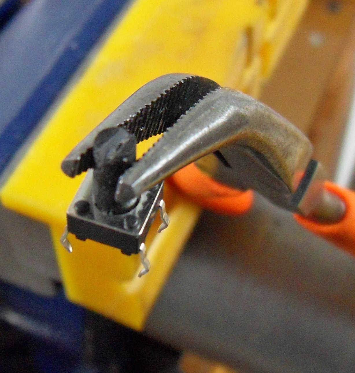
Superglue used to hold a round 5mm LED to a standard tactile push button. (I think I saw this concept used on HAD previously but couldn't locate the original post.) Result is a LED that protrudes from the face plate and can be pushed to activate the push button. The top of the button was filed to create a grove to provide some clearance for the LED leads. This provided enough contact between the top of the button and base of the LED for the superglue. The push button is soldered to the PCB as normal. The LED leads are soldered to a looped piece of stranded wire to make the connection to the PCB. This allows it to move freely when pushing the button. My concept for the controls required one Red/Green LED and 4 Green LEDS. The Red/Green ones on hand were frosted case and the green ones were clear. I ended up filing them all flat on the top and sanding the sides for a uniform appearance. This looks more button like and diffuses the light for better viewing angle.
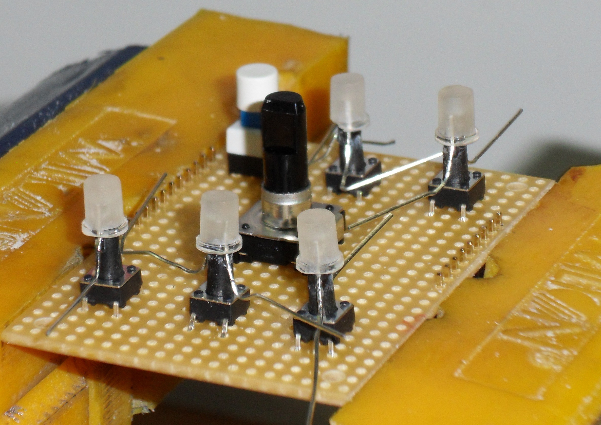
The 6 LED/Buttons and rotary encoder were laid out on some prototyping board and a plastic blank wall face plate. They fit fairly well and the height of the PCB from the wall plate was figured out. The plastic wall plate was too flimsy, pushing on the face plate could cause the buttons to depress. A white painted metal face plate was located at the hardware store. The button labels and drill center marks were laid out with CAD software. Toner transfer method was used to copy the layout and button labels to the metal face plate. Roughing up the wall plate with steel wool before performing the transfer seemed to work well. After drilling, the face plate was sprayed with clear gloss to protect the labels.
Cramming all the through-hole parts on one PCB didn't seem practical. A 2 layer strip board PCB design was worked out using header pins and sockets to connect the boards and allow disassembly. ¼-inch polycarbonate scrap was used to fabricate mounting blocks with 4-40 threads. These were glued to the back of the metal wall plate. A pair of stand offs were used to sandwich the PCB with the buttons and rotary encoder. Spacers and screws were used to mount the main PCB.
The RS232 level converter is setup in typical arrangement. Early on in the project, the level converter and MCU were tested to verify the thermostat / s-video cable arrangement would handle the communication without problems. During this testing, scope was hooked up to see how much noise the converter was generating. The standard 0.1 µF capacitors were increased to 0.22 µF to try to minimize the noise. This did not seem to help much. After more troubleshooting, the current draw was found to be about 40mA instead of the 2-3 mA expected when not transmitting. I had grounded the unused T2OUT and R2OUT pins. This was draining the outputs causing the high current. Only the T2IN and R2IN needed to be grounded to keep the T2OUT and R2OUT stable. This also took care of the noise, but I left the 0.22 µF anyway.
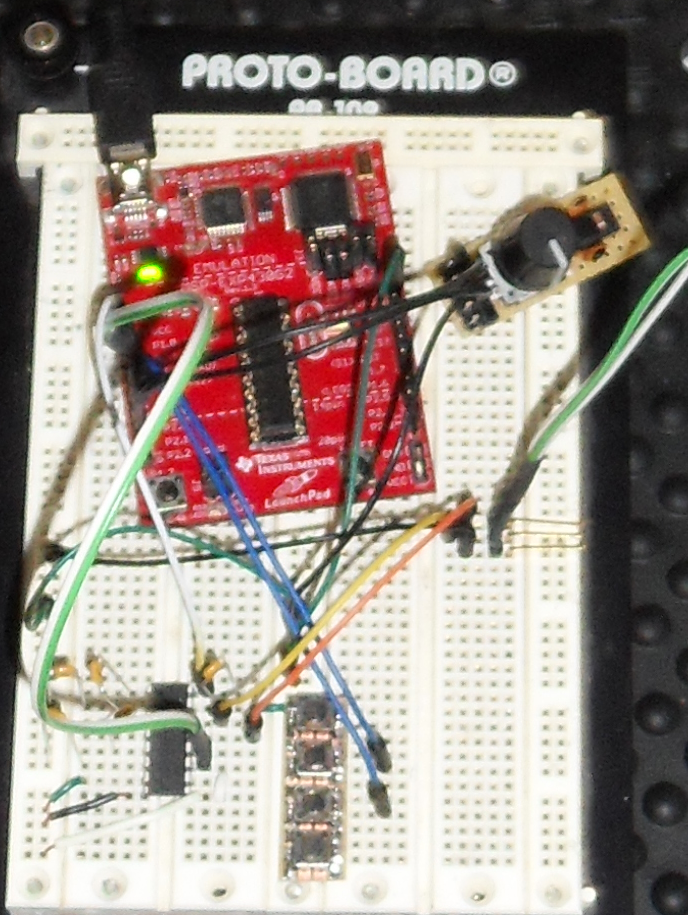
The MSP430G2353 includes a universal serial communication interface (USCI_A0) peripheral that makes implementing the RS232 communication in software fairly easy. Half of the memory was dedicated to circular buffers for characters received or to be sent. Commands and responses to/from the receiver use \r to terminate. When a \r is received the rx buffer is processed to see if it is status or a response of interest to the controller. When sending commands, the buffer tx is loaded including the \r and the the tx interrupt triggered.
This was my first rotary encoder project so this was prototyped as well to test the hardware and software. The Google results are littered with state machine type decoding of the knob movement. The more efficient way is to create a value using the prior and current states of A & B and then use this value to in a lookup array to get the knob movement. I could not locate the original example tutorial I used for developing my code but found this one that provides an excellent summary (http://www.mkesc.co.uk/ise.pdf). The encoder I used had detentes for each click of the dial so some logic was added to make each click change the volume by one value. Both A & B channels were connected to PORT2 GPIO with only the LEDs on the other PORT2 pins. Initial toughs were this would be used to separate the interrupts for button presses and knob movement. Ended up just polling the inputs with a fast timer to help with debouncing.
//Globals
signed const char enc_states[] = {0,-1,1,0,1,0,0,-1,-1,0,0,1,0,1,-1,0};
unsigned char old_AB=0;
int quadCounts=0;

//0.5 ms timer interrupt service routine
old_AB <<= 2;               //remember previous state
old_AB |= ( P2IN & 0x03 );  //add current state
                            //BIT0 and BIT1 are rotary encoder A & B inputs

int temp = enc_states[( old_AB & 0x0f )];  //bits 0 to 3 are masked out to
                                           //get one of the 16 values in the enc_states array

if (temp !=0)
{
   //Keep track of the pulses
   quadCounts += temp;

   if (quadCounts==4)
   {
      //1 detent counter clockwise, set flags to lower volume and wake up
      quadCounts=0;
      button=BUTTON_DOWN;
   }

   if(quadCounts== -4)
   {
      //1 detent clockwise, set flags to raise volume and wake up
      quadCounts=0;
      button = BUTTON_UP ;
   }

}
A four pin right angle connector was added to the board with the required 47k resistor for in-circuit programming and debugging. With the IC sandwiched in between the two PCBs, removing the chip to program would require removing the screws and would get old real fast. A connection to 3.3V wasn't included so the unit needs to be connected to the receiver and powered or a separate 5v power applied to the correct pins on the input header.
Schematic and software are available using the Github links. The controller allows for the Zone 2 power to be turned on or off from the wall plate. The status led (Zone2) is red when zone2 is off and green when zone2 is on. If the receiver was off and status pressed to turn on, there is an 8 second delay before audio is output and indicated by a green flashing status led. The status red flashes a slow red when there is no RS232 connection and a flashes red and green (orange) quickly if there is an RS232 error. The mute button commands minimum volume or restores the last volume level when pressed. It is solid green when volume is muted. The 3 source buttons change the zone 2 source when pressed. Multiple presses of the tuner source button change the radio stations between 6 hard coded presets. Finally the rotary encoder controls the volume level.