 Jorj Bauer
So you saw a little bit of this in operation in Phase 2, where I tested the shoulder motors. Having never built a robot before, the motors were what I considered the most challenging part - I don't know what parts exist, what the problems might be, or how to even describe what I need. Other than to say "Bob weighs about 25 lbs. and I want him to move at about walking speed."
The general design: two motors and wheels in the base, near the back, which will drive the unit; two rolling balls in the front, so that I'm not dealing with the rotation of a caster wheel, defeating quick turns; two motors up top, rotating the shoulders. 12v, so I can run it from a motorcycle battery.
I picked a couple of motors pretty much at random off the Internet - a pair of 1:70 12v motors with ~80mm wheels. These were too fast for the shoulder and too slow for the main drive (also: not enough torque for the main drive, which was my first hint that this series of motors might barely be passable, but would probably never be good).
I don't have a lot of the build process documented, so let's do some retro-documentation here...

Obviously, you see several generations of work here. Originally there were no motors; I didn't know if I'd have time to finish them before LIWhoCon 2014. So there were three rolling balls and it was just a model, no remote control or electronics. All three were plastic (one is stainless steel in this shot - the spare, in the back).
But I did have the time. When I first went with motors, I mounted them in the front. That didn't work very well for reasons I don't remember, and I moved them to the back. The first set of motors I installed were too low powered, and I went with a pair of 100:1 ("37GB") 200rpm 12v motors that had enough torque - barely. And are too slow; probably somewhere under 2mph. (Math says: 80mm wheels and 200rpm = 1.86 mph.) So it's painful to walk alongside this while you're remote-controlling it from place to place. But it works.
The wheels have a rubber tire ring around a plastic wheel. The rubber stretched badly from the strain of moving this thing, and I abandoned rubber in favor of plasti-dip. Which wore off badly at the con in just a few hours. I wound up re-dipping them in our hotel room overnight. Now, they're covered in truck bed liner which is much, much better. (Thanks to someone at ProjectDalek for the hint on this one.)
The plastic wheels didn't fare well either. The plastic got badly chewed up, and I lost one ball in an elevator (used the spare!). In 2015 I wound up replacing them with steel balls that wouldn't get chewed up, but lost two of the three, and popped in the plastic replacements that I had with. I'm not sure any of these is sufficient, really, since I keep destroying and losing them.
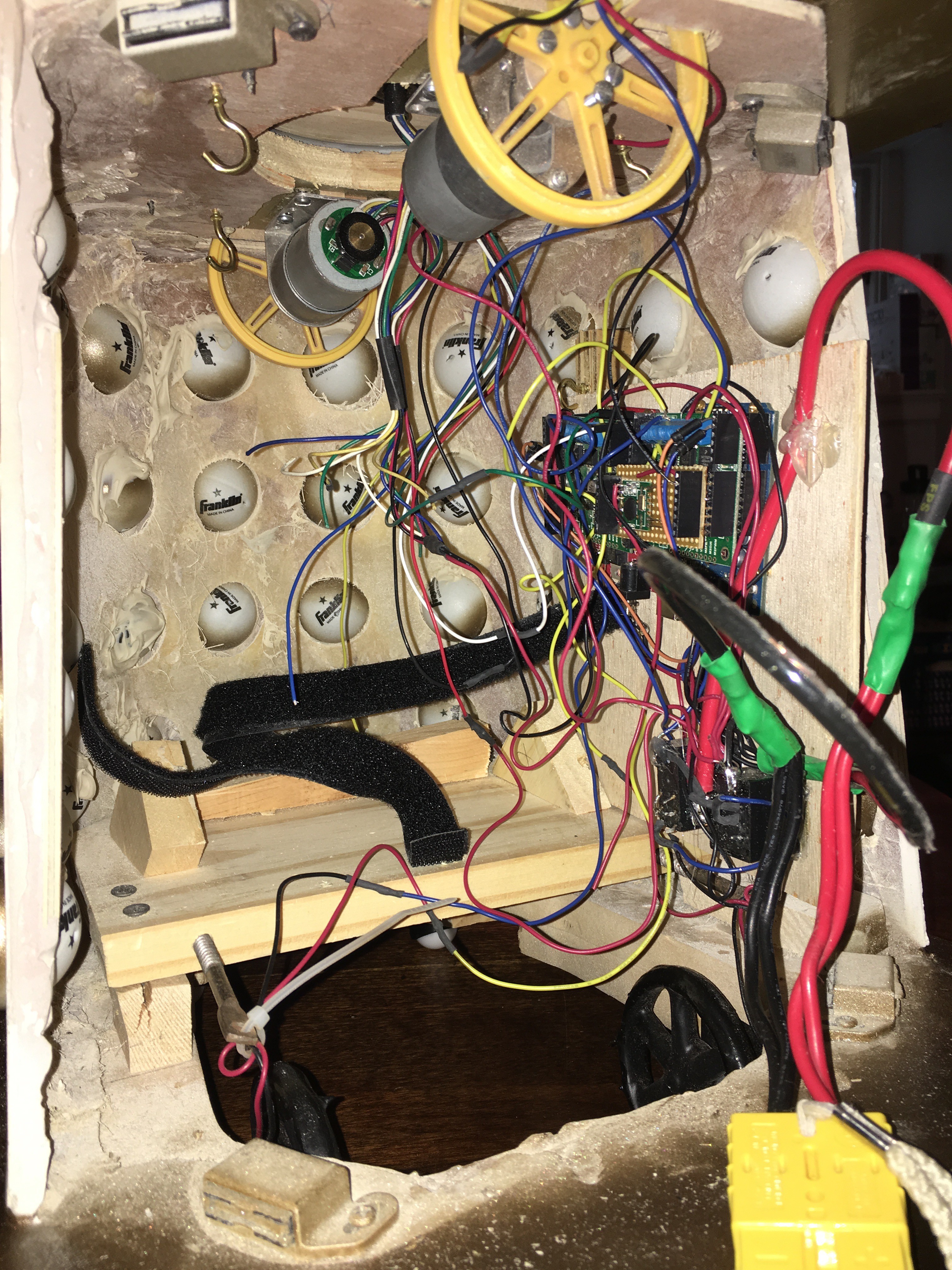
Here's the view on the inside, from the back hatch: the two yellow wheels on the top, and their motors, are driving the shoulder rotation. The force of gravity holding the top down (it's *really* heavy due to all of the bondo) is enough to keep good contact against the plastic of the wheels; no rubber (or rubberizing) required.
Here's the primary circuitry, mounted on a piece of luan that slides in next to the battery carrier.
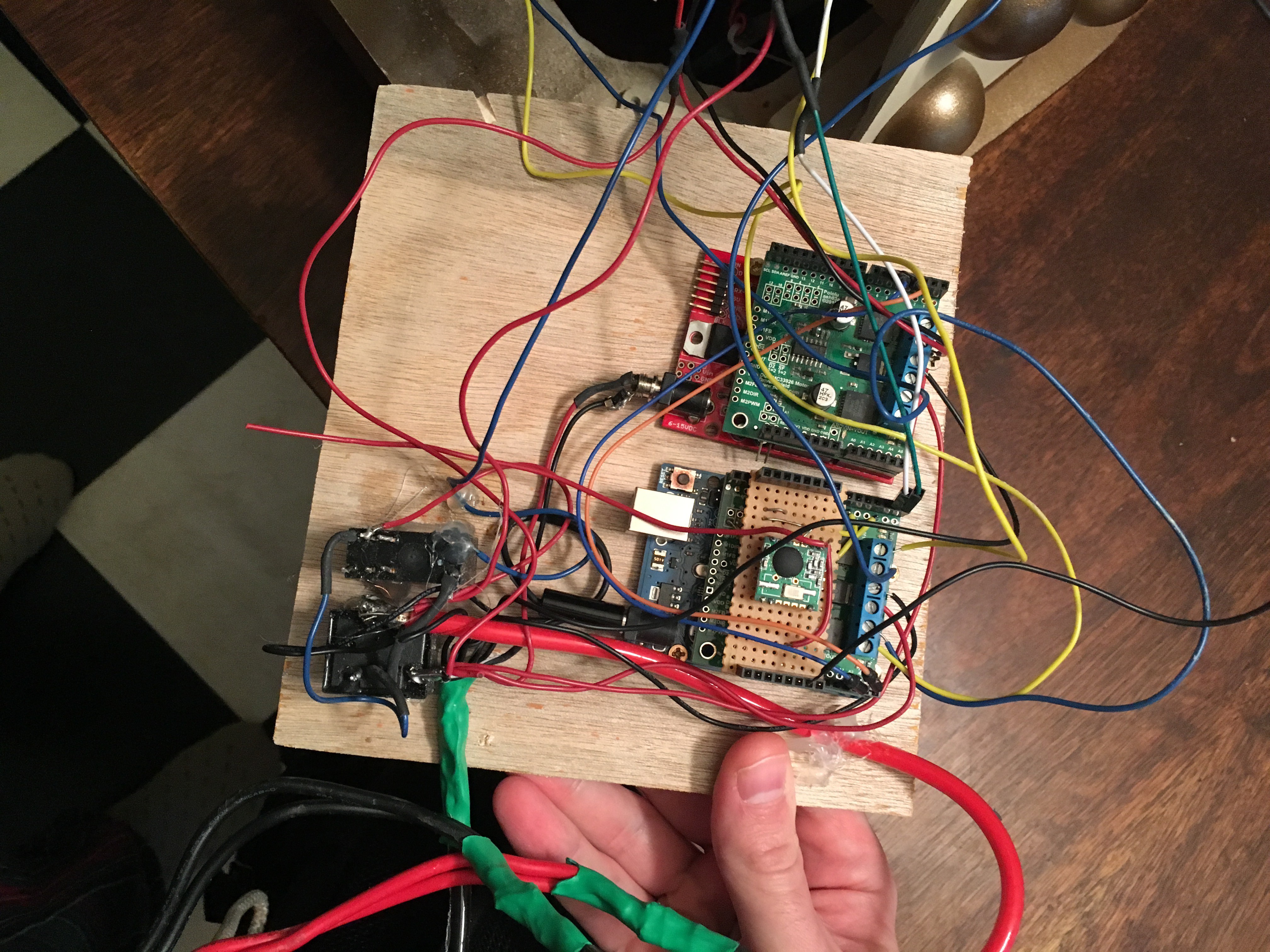
The two things in the lower left are relays. One trips the other, for reasons I don't remember - but if I had to guess, it's because I wired it all up to one, and it didn't work properly, but the other one did, so I used one to trigger the other? If that's true I must have done it in the field. And I do remember that there was a stress fracture of something at the hotel the first year and I melted down some of the case of a relay to get enough metal exposed to reconnect it. So that's probably what happened.
This obviously could use some re-work. Which you'll hear more about later.
Then there are two arduino boards. The lower-right one is the master board. It does three things:
* RFM12B receiver (the protoboard on the top);
* Primary motor drive (terminal blocks just under it);
* Communication with the other boards in the unit (doling out commands that come in over RF).
The upper-right board drives the shoulder motors and nothing else.
There's also a third Arduino up in the head (connected through a 5A 6-wire conducting slip ring) that runs the audio with the help of a WAV shield and a CF card that has a bunch of audio files on it. You can also see a small amplifier in the upper-right, just before it connects to that speaker.

I want to say two things about my use of Arduinos here.
First: I used way too many of them because it was easy. Good engineering takes time. I didn't have time. I built a first-generation "it works, but not efficiently" system. This is, I firmly believe, good. It gives you the opportunity to understand the actual system requirements as you design, so that you can later design something that's better; it gets you a result fairly quickly, which lets you focus on the end-result instead of the intermediate details; it keeps you from prematurely optimizing something that's not actually a problem. There is nothing wrong with inefficiency and overkill in the first rev of anything. In subsequent revisions, you clean it up and make it more efficient. This is how successful engineering works on small scale, period.
Second: I prefer to hand-code assembly in PICs rather than using Arduinos and their IDE. But that takes time, and is more about crafting the code than about getting the result. I didn't have time for that here, so I fell back to the Arduinos for which libraries and hardware existed to do what I needed, on my timeline. The Arduino ecosystem is clearly an advantage for rapid prototyping, and I find myself using them a lot more than PICs these days.
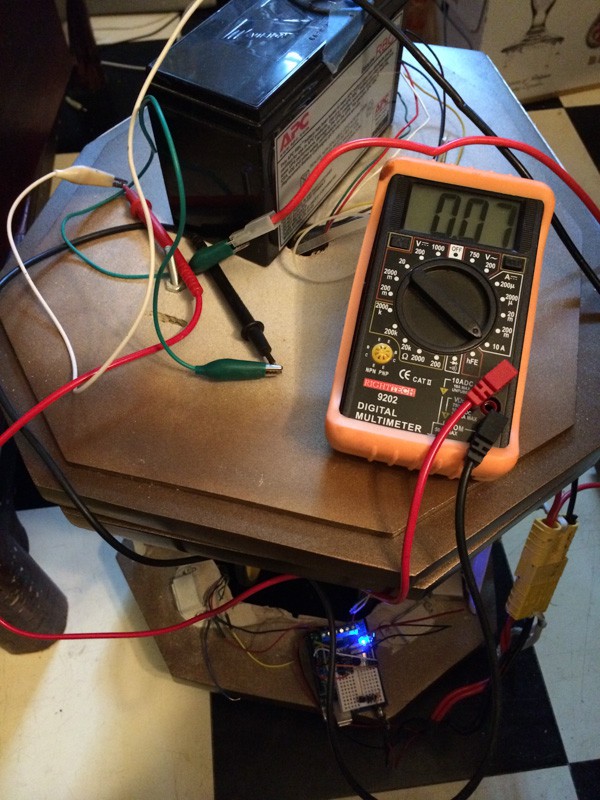
Once I had the bare bones together, I needed to understand the power requirements. I had no idea what the draw would be, and I was hoping to run it off of a motorcycle battery (because I had a few, scavenged from dead UPSes).
This was the first power test - 70mA draw quiescent (that's the arduinos), and about 3A full bore (that's the motors). Fine; I'll take a couple of batteries with me, and swap as necessary.
So with all of that looking fine, there's just the remote to build.
The first generation remote had two buttons to swivel the head, and a joystick to move the Dalek (vector math FTW). The long switch top-center is power, with a little power LED next to it, and the sliding switch to the right was to control whether Bob was in "slow" or "fast" mode. The whole thing is run by a Pro Mini 3v, and talks via RFM12B.
This remote worked reasonably well until we added the sound system. Now we needed to also select what kinds of sounds to play. And I realized that other people at the con would want to drive it around, and this is not exactly the most user-friendly remote.
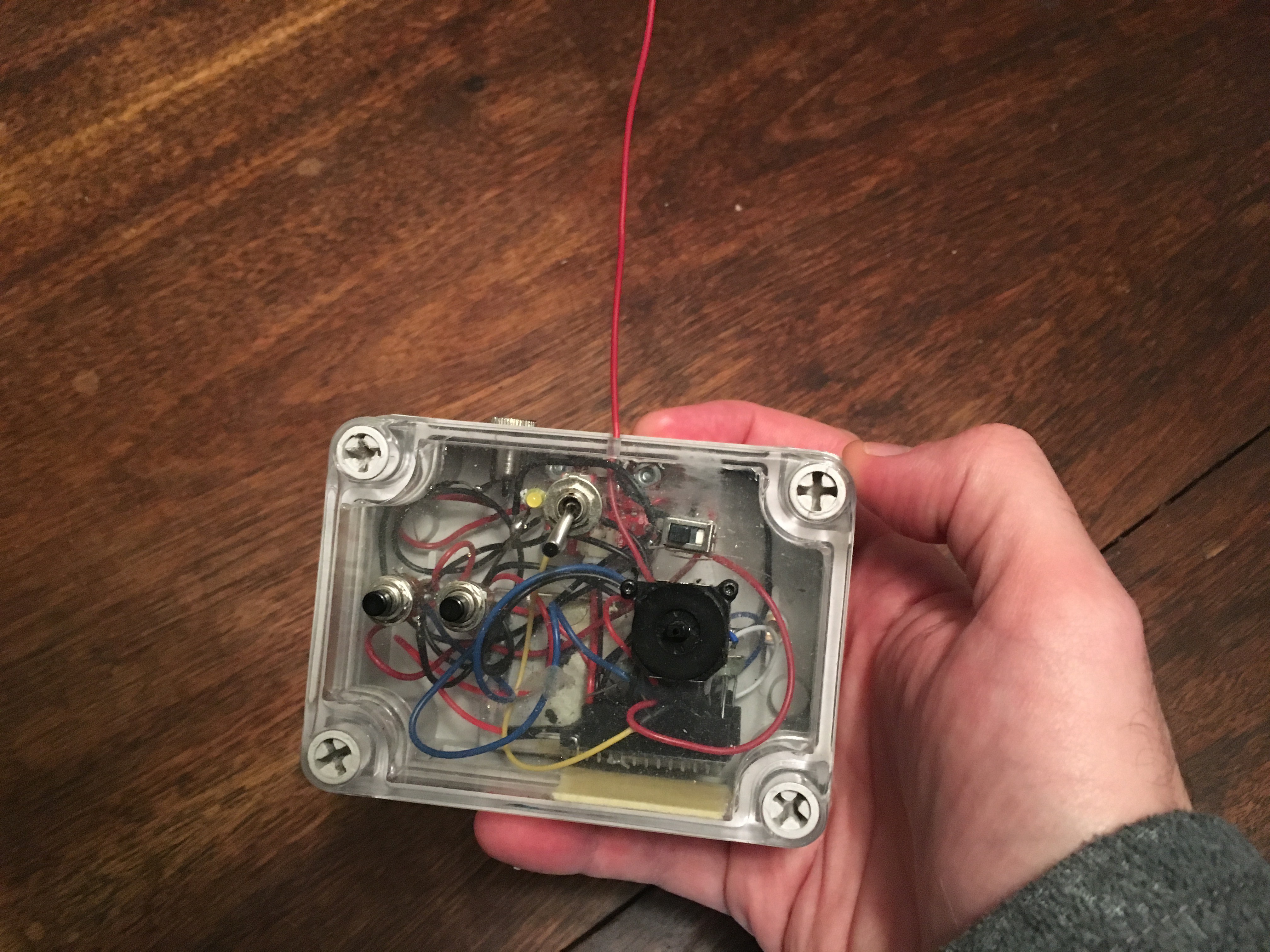
I spent some time thinking about what the right interface would be, and finally decided to build rev2 inside a generic Wii controller.
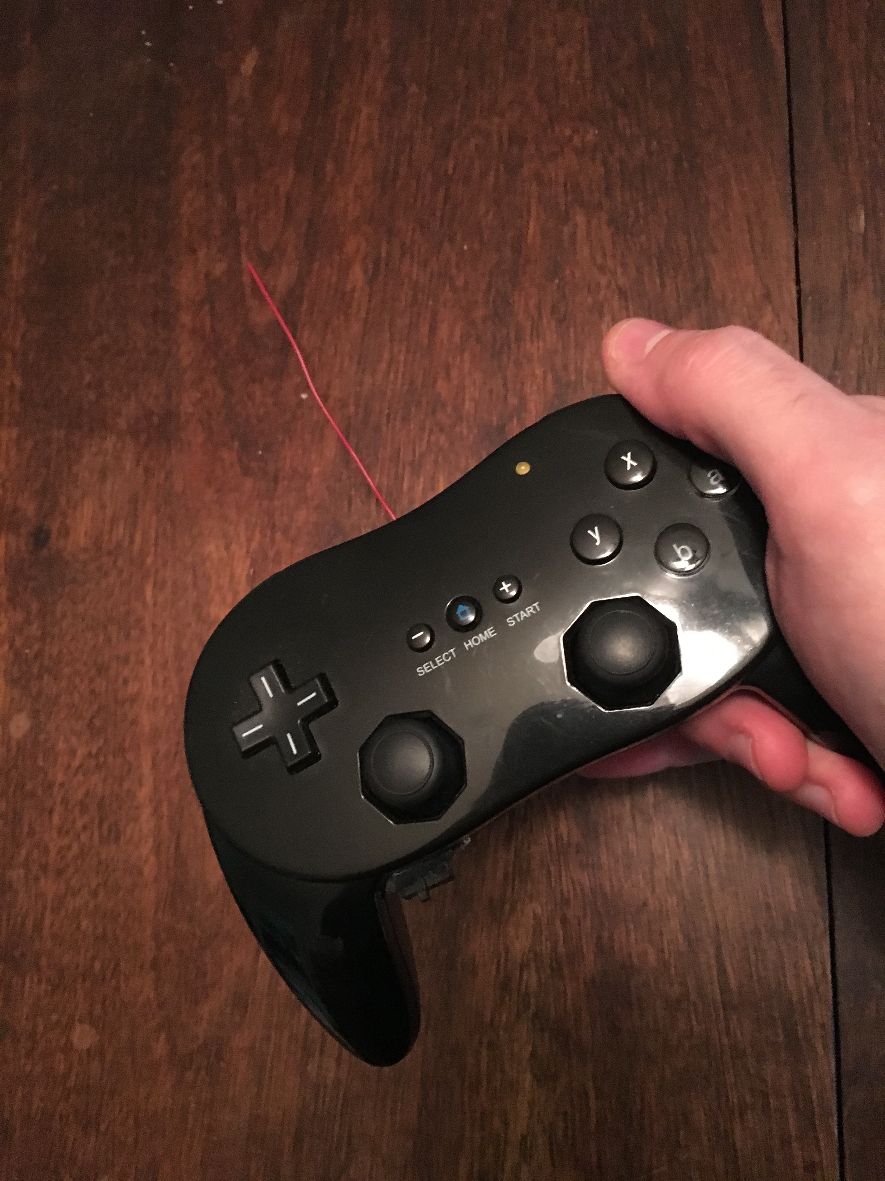
This is a tight build.
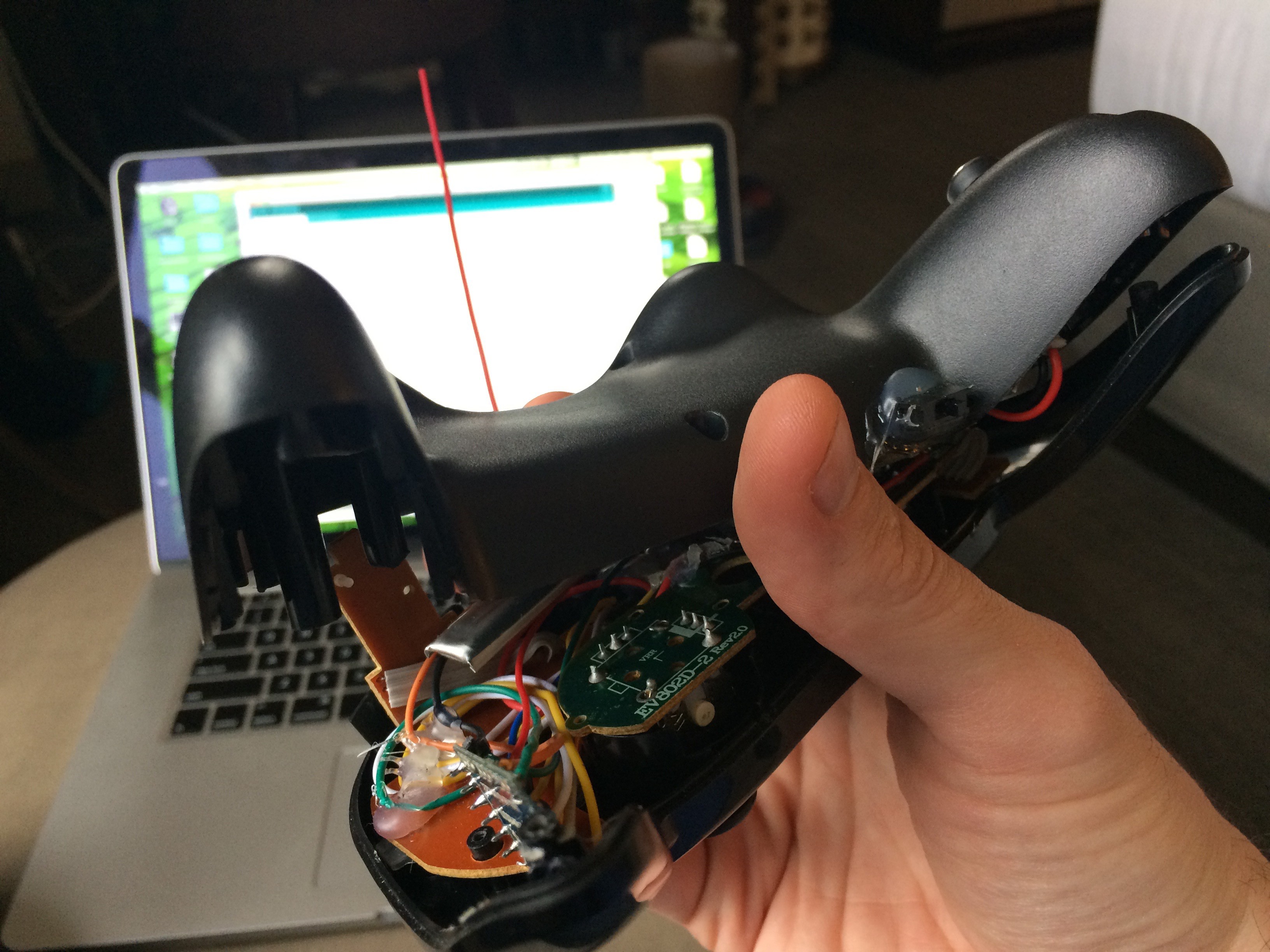
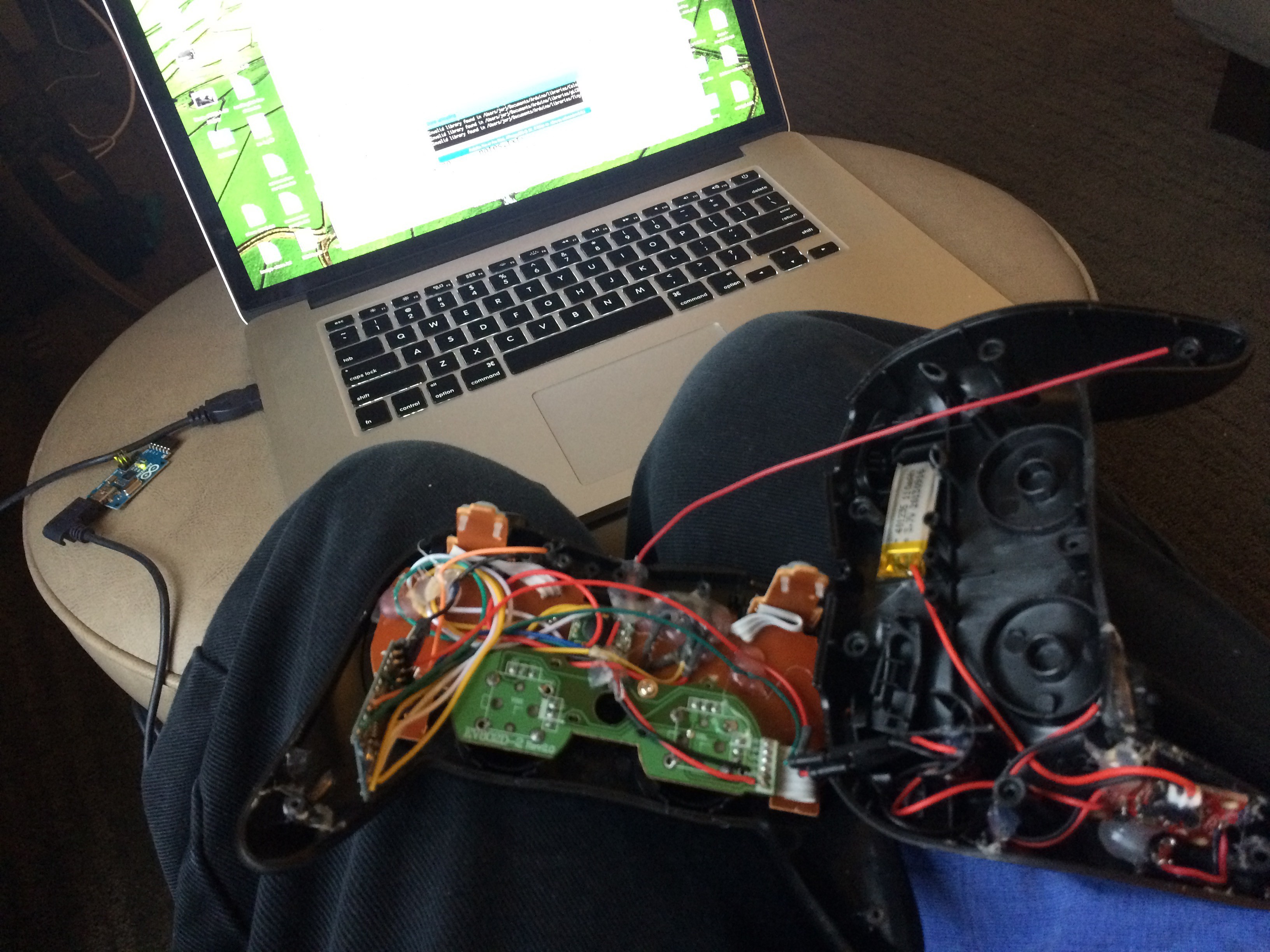
Somewhat more open, here it is again - the battery in the right, along with the charging circuit; and the pro mini in the lower-left:
So, does it work?
It's not ideal, but it functions! You can see that when it loses traction on the carpet, there's a lot of shaking because of how I'm driving the motors (trying to achieve the most efficient turn by driving one motor backward and the other forward). I eased up on the algorithm a bit to reduce the shaking after this test; not much else needed tweaking though.
Discussions
Become a Hackaday.io Member
Create an account to leave a comment. Already have an account? Log In.