As I've previously mentioned, one of the main project goals is to use only a single servo dedicated to leg movement, rather than the two that are currently required. I've found it difficult to visualize a completely satisfying solution to the problem and I have instead decided to focus mainly on the steering issue for the time being. That priority hasn't changed, but I believe I made a breakthrough today. And since it's now nighttime and I can't sleep I might as well write a log about it.
I'll be rambling on a bit first though, so scroll down to the last paragraph if you just want the solution.
Problem definition
In a previous log I describe the sequence of leg movements Landbeest uses for walking. It consists of a continuous cycle of four poses: A, B, C and D.
The leg poses are controlled by two linear actuators. Let's call these L and R. They have only two resting states: Max and Min. Below is a diagram that relates the resting states of L and R to each pose.
| L | R | Pose |
| Max | Min | A |
| Max | Max | B |
| Min | Max | C |
| Min | Min | D |
In the transition between two poses, an actuator either moves to its opposite state or remains inactive. Only one actuator moves at any transition.
My old crappy solution
There are three major parts to this problem that has made it a little tricky for me to work out a solution:
One part of the problem is how to achieve reciprocating linear motion.
With the current 2-servo design i used servos with 180 degree rotation mounted in this linear sprocket actuator I got off Thingiverse. That's fine as long as there's one servo per actuator, but not if one servo is supposed to move both. For a 1-servo design I'd need to use a continuous 360 degree servo instead. (I'm kind of glossing over how I came to that conclusion, sorry about that.) There's a couple ways of converting rotation to back-and-forth linear motion. I decided on the mechanically simple method used by this device.
The second part is that each actuator should only move half of the time. To do that for a single actuator isn't that hard:
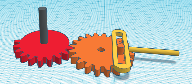
The red gear is connected to the servo and spins continuously in one direction. It's only toothed halfway around so each turn will rotate the orange gear by half, move the yellow actuator to it's opposite extreme position, after which it's stationary for the rest of the red gears turn.
So that's the L actuator taken care of. The third part is where it gets crazy:
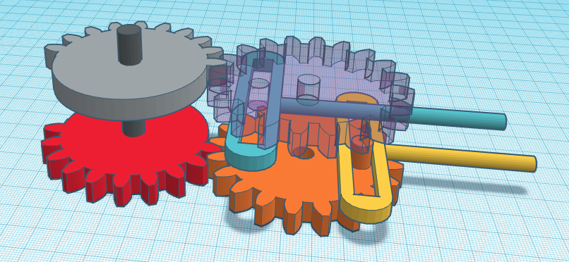
Yeah! So the gray gear is coupled to the same servo shaft as the red gear. It does the same thing for the R actuator (blue) as the red gear does for L, only delayed by one half turn of the servo. It's hard to tell from the picture, but the transparent gear is identical to the orange one only turned upside down. Here's the same image without the transparency:
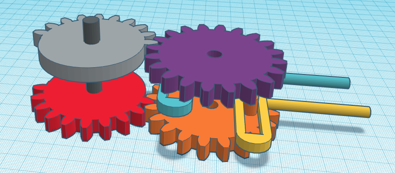
While I see no reason why this won't work in theory, there sure are plenty of practical issues with it. Assembling the parts could be quite tricky since each gear must interlock with the right tooth of its neighbor. The assembly must be contained in a housing where the orange gear is mounted to the floor and the purple gear to the ceiling. But the most damning problem is that there's nothing in the mechanism itself that stops the orange and purple wheels from slipping out of alignment while they're not engaged. And I can't think of any worthwhile add-on to remedy that.
The right (?) solution... (Yes I believe it is!)
I finally saw the light today when I was browsing Youtube for some sweet reciprocating piston action and stumbled over this video:
I learned two things from it: First that the wheel and piston assembly I've been using is called a "Scotch yoke". But the major revelation was that you can pause the linear action by introducing a "dwell". That wobbly groove solves all the problems I've been wrestling with in one fell swoop.
I can ditch the half-toothed gears and mount the servo directly to the yoke wheel instead. I can then add a second piston (R) on top of the first one (L), both coupled with the same peg. Only difference is the second piston has its dwell mirrored. That's it in a nutshell.
Finding out about the dwell also brought home how restricted your thought process really is most of the time. Scary. So I guess I learned three things.
I'm sure a mechanical engineer would have solved this problem in a minute, but I must say I'm really satisfied having finally cracked this nut. For me it was a hard one.
Also I'm really sleep deprived at the moment, so I might be overlooking something that will uncrack that nut again. Guess I'll find out tomorrow when my brain starts working again. (Today really—it's 4 am.)
Discussions
Become a Hackaday.io Member
Create an account to leave a comment. Already have an account? Log In.