 stefan.schnitzer
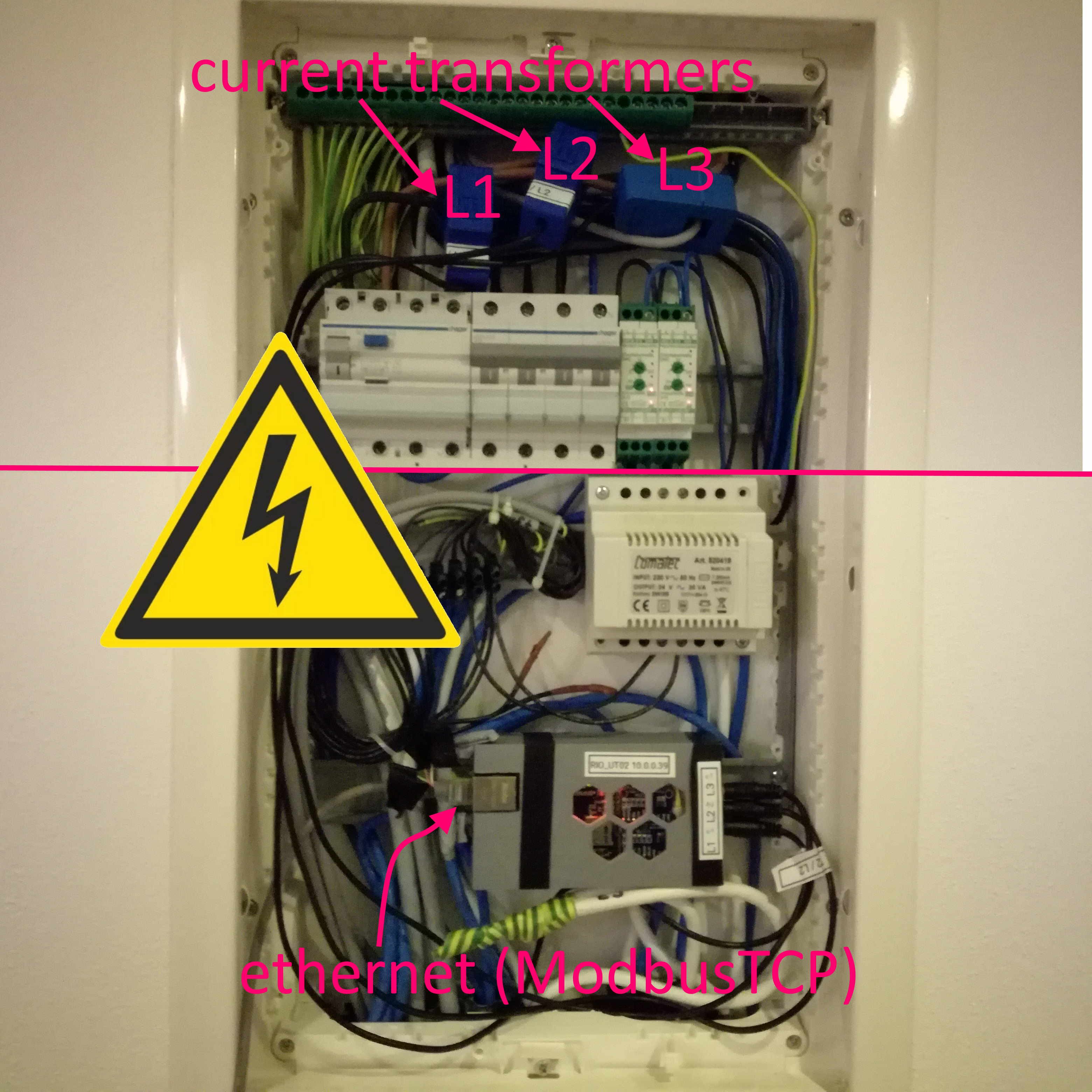
Now it's time for the first field test. I assembled the 3d-printed case (with some tape) and installed the current transformers in my mains input. (Fortunately, there were 4 free wires on a cat cable that brings DSL to my modem/router)
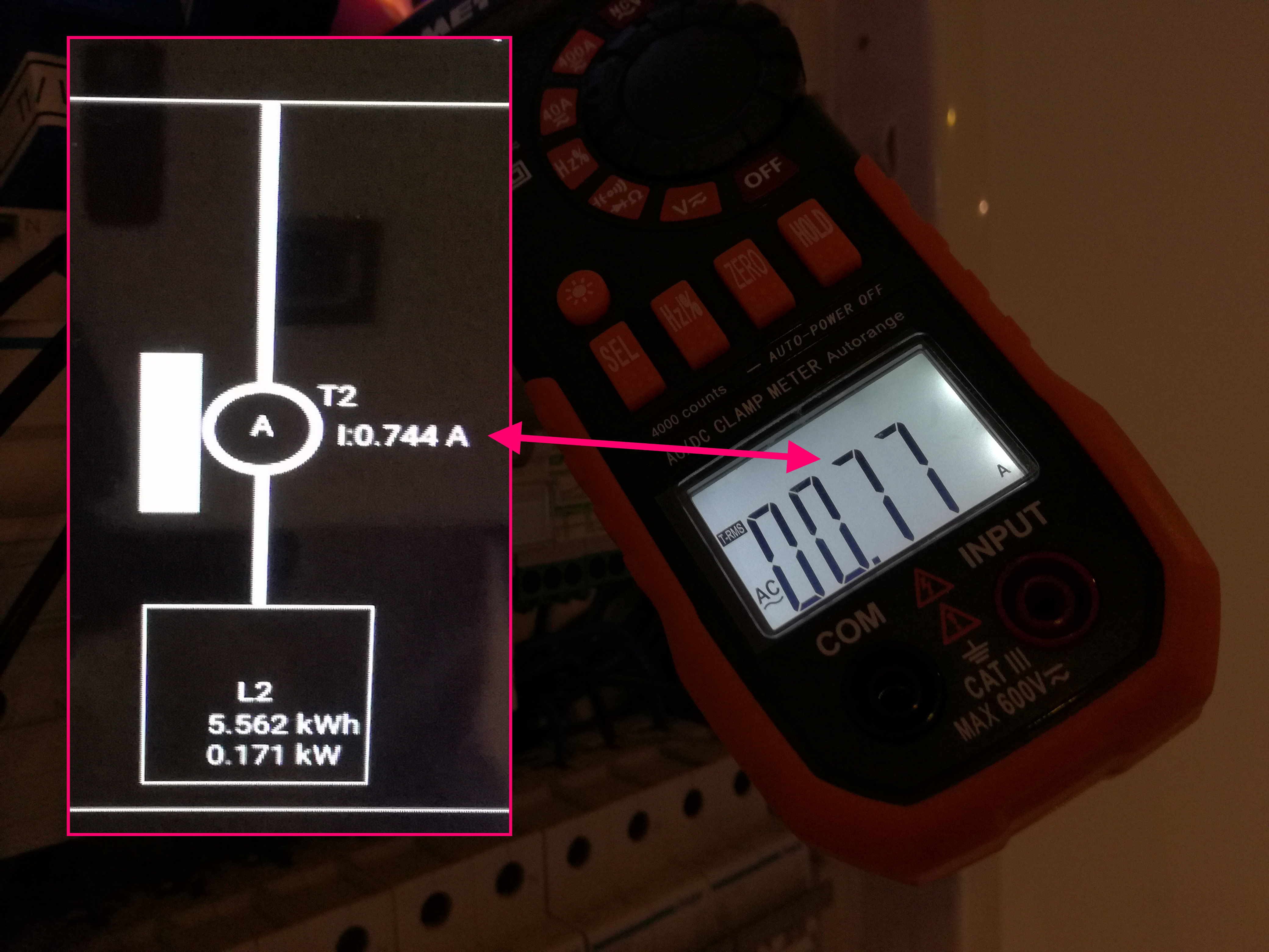
After that, I was able to check the values transmitted to the smart home with a clamp amp meter.
-> field test passed -> design and 3d print a better case (with DIN-rail mounting brackets)...
Discussions
Become a Hackaday.io Member
Create an account to leave a comment. Already have an account? Log In.