 Silícios Lab
Introduction
Several people develop projects with robotics and one of the big problems is determining their navigation direction. In other words, the robot moves around the environment, but the system does not know its exact direction and this implies the process of its navigation.
As a solution, many people adopt the use of the GPS device to assist in the process of determining the direction. However, due to its commercial financial value, the project becomes more expensive and makes it impossible to use it to determine only the navigation direction.
In this case, the ideal is to use a magnetometer sensor. It has the ability to determine the direction of guidance from low financial investment in the project. That way, you will be able to determine your robot's navigation direction.
In this article, you will learn how to build your own digital compass with Arduino. Through it, you will be able to learn the complete operation of the HMC5883L sensor, to detect its orientation direction.
In addition, you will learn how to build your own electronic compass board and use it with your Arduino. In Figure 1 is shown the printed circuit board of the digital compassing.
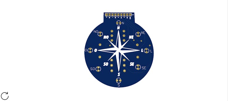
Figure 1 - Printed Circuit Board of the Digital Compassing.
Therefore, at the end of the article you will have learned the following points:
- Creation of a digital compass with Arduino;
- Operation of the HMC5883L sensor;
- Creation of the Compass Printed Circuit Board with Arduino;
- Win the Compass printed circuit board files with Arduino.
Project Development
This project will be divided into 3 important stages: Construction of the compass printed circuit board, Arduino circuit with the HMC5883L sensor and code for the Arduino to control the digital compass on the printed circuit board.
First, we are going to present the construction of the digital compass circuit. Next, we will present the circuit structure with the Arduino and the HMC5883L Magnetometer sensor.
Finally, we will present a basic program to control the digital compass on the printed circuit board.
1. Development of the Digital Compass Printed Circuit Board
To start the development of the printed circuit board of the digital compass, it was necessary to develop the circuit with 8 LEDs and a 9-pin male connector.
Each LED represents a specific direction of the compass rose. The circuit is shown in Figure 2.

Figure 2 - Electronic Schematic of the Digital Compassing.
After the construction of the electronic schematic, the electronic board was developed. The PCB design is shown in Figure 3.

Figure 3 - Printed Circuit Board of the Digital Compassing.
After the construction of the electronic board project, we can see its structure just below in Figure 4.

Figure 4 - Compass Rose PCB.
Now, I will show you how to build the circuit with the Arduino and the HMC5883L sensor. From this circuit, we will be able to detect the orientation of the robot and then activate the specific LED of the compass rose.
2. Circuit Development of the Arduino with the HMC5883L Sensor
In the circuit below we present the Arduino Nano connected with the HMC5883L sensor.
The HMC5883L sensor is responsible for detecting the direction from North to South, and then the Arduino will receive and process this information.
From there, the Arduino will trigger one of the outputs from D2 to D9. These outputs will be connected to the board developed in step 1.
Therefore, each LED will represent a specific direction. The Electronic Schematic is presented in Figure 5,

Figure 5 - Electronic Schematic of the Arduino and Sensor HMC5883L.
Now, we'll present the programming of the project presented above.
3. Arduino Programming Project
First, we present the complete logic of the project's programming.
#include <Wire.h> //Biblioteca de Comunicacao I2C
#include <MechaQMC5883.h> //Biblioteca do Sensor QMC5883 - Modulo GY-273

MechaQMC5883 bussola; //Criacao do objeto para o sensor

int x = 0, y = 0, z = 0;
int angulo = 0;

void setup()
{    Wire.begin(); //Inicializacao da Comunicacao I2C    Serial.begin(9600); //Inicializacao da comunicacao Serial    bussola.init(); //Inicializando o Sensor QMC5883    for(byte pino = 2; pino <= 9; pino++)    {     pinMode(pino, OUTPUT);    }
}

void loop()
{
  bussola.read(&x,&y,&z); //Obter o valor dos eixos X, Y e Z do Sensor  angulo = atan2(x, y)/0.0174532925; //Calculo do angulo usando os eixos X e Y atraves     da formula

//Ajuste do angulo entre 0 e 360 graus
if(angulo < 0)
angulo+=360;
angulo = 360-angulo;

Serial.println(angulo); //Imprime o valor do angulo na Serial do Arduino
//Apresentando o sentido com base no angulo encontrado

if (angulo > 338 || angulo < 22)
{
digitalWrite(2, HIGH);
digitalWrite(3, LOW);
digitalWrite(4, LOW);
digitalWrite(5, LOW);
digitalWrite(6, LOW);
digitalWrite(7, LOW);
digitalWrite(8, LOW);
digitalWrite(9, LOW);
Serial.println("Norte");
}

if (angulo > 22 && angulo < 68)
{
digitalWrite(2, LOW);
digitalWrite(3, HIGH);
digitalWrite(4, LOW);
digitalWrite(5, LOW);
digitalWrite(6, LOW);
digitalWrite(7, LOW);
digitalWrite(8, LOW);
digitalWrite(9, LOW);
Serial.println("Nordeste");
}

if (angulo > 68 && angulo < 113)
{
digitalWrite(2, LOW);
digitalWrite(3, LOW);
digitalWrite(4, HIGH);
digitalWrite(5, LOW);
digitalWrite(6, LOW);
digitalWrite(7, LOW);
digitalWrite(8, LOW);
digitalWrite(9, LOW);
Serial.println("Leste");
}

if (angulo > 113 && angulo < 158)
{
digitalWrite(2, LOW);
digitalWrite(3, LOW);
digitalWrite(4, LOW);
digitalWrite(5, HIGH);
digitalWrite(6, LOW);
digitalWrite(7, LOW);
digitalWrite(8, LOW);
digitalWrite(9, LOW);
Serial.println("Suldeste");
}

if (angulo > 158 && angulo < 203)
{
digitalWrite(2, LOW);
digitalWrite(3, LOW);
digitalWrite(4, LOW);
digitalWrite(5, LOW);
digitalWrite(6, HIGH);
digitalWrite(7, LOW);
digitalWrite(8, LOW);
digitalWrite(9, LOW);
Serial.println("Sul");
}

if (angulo > 203 && angulo < 248)
{
digitalWrite(2, LOW);
digitalWrite(3, LOW);
digitalWrite(4, LOW);
digitalWrite(5, LOW);
digitalWrite(6, LOW);
digitalWrite(7, HIGH);
digitalWrite(8, LOW);
digitalWrite(9, LOW);
Serial.println("Suldoste");
}

if (angulo > 248 && angulo < 293)
{
digitalWrite(2, LOW);
digitalWrite(3, LOW);
digitalWrite(4, LOW);
digitalWrite(5, LOW);
digitalWrite(6, LOW);
digitalWrite(7, LOW);
digitalWrite(8, HIGH);
digitalWrite(9, LOW);
Serial.println("Oeste");
}

if (angulo > 293 && angulo < 338)
{
digitalWrite(2, LOW);
digitalWrite(3, LOW);
digitalWrite(4, LOW);
digitalWrite(5, LOW);
digitalWrite(6, LOW);
digitalWrite(7, LOW);
digitalWrite(8, LOW);
digitalWrite(9, HIGH);
Serial.println("Noroeste");
}

delay(500); //Delay de 500 ms entre novas leituras
}
Now, we will start discussing each part of the developed code.
First, we declare the libraries, the "bussola" object and we declare the program variables. The region of the code is presented below.
#include <Wire.h> //Biblioteca de Comunicacao I2C
#include <MechaQMC5883.h> //Biblioteca do Sensor QMC5883 - Modulo GY-273

MechaQMC5883 bussola; //Criacao do objeto para o sensor

int x = 0, y = 0, z = 0;
int angulo = 0;
After that, we enter the function void setup. Inside it, we initialize the serial and I2C communication and then we initialize the magnetometer sensor.
Finally, we set digital pins 2 to 9 as the output. These pins will be used to drive the LEDs on the printed circuit board. The portion of the code is presented below.
void setup()
{    Wire.begin(); //Inicializacao da Comunicacao I2C    Serial.begin(9600); //Inicializacao da comunicacao Serial    bussola.init(); //Inicializando o Sensor QMC5883    for(byte pino = 2; pino <= 9; pino++)    {     pinMode(pino, OUTPUT);    }
}
After the complete execution of the void setup function, we will enter the void loop function. In this function, the main logic of the project will be executed.
First, we read the x, y and z axes of the sensor and then we perform the conversion to angle calculation.
bussola.read(&x,&y,&z); //Obter o valor dos eixos X, Y e Z do Sensor angulo = atan2(x, y)/0.0174532925; //Calculo do angulo usando os eixos X e Y atraves da formula
Subsequently, we convert the angle value into the range of values between 0 and 360 degrees. The adjustment calculation is presented in the following condition.
//Ajuste do angulo entre 0 e 360 graus
if(angulo < 0)
angulo+=360;
angulo = 360-angulo;
Therefore, from the calculation of the angle obtained, we will apply the value in the following conditions. Each angle value represents a different orientation.
This way, based on the current angle, it will trigger an LED on the digital compass plate.
if (angulo > 338 || angulo < 22)
{
digitalWrite(2, HIGH);
digitalWrite(3, LOW);
digitalWrite(4, LOW);
digitalWrite(5, LOW);
digitalWrite(6, LOW);
digitalWrite(7, LOW);
digitalWrite(8, LOW);
digitalWrite(9, LOW);
Serial.println("Norte");
}

if (angulo > 22 && angulo < 68)
{
digitalWrite(2, LOW);
digitalWrite(3, HIGH);
digitalWrite(4, LOW);
digitalWrite(5, LOW);
digitalWrite(6, LOW);
digitalWrite(7, LOW);
digitalWrite(8, LOW);
digitalWrite(9, LOW);
Serial.println("Nordeste");
}

if (angulo > 68 && angulo < 113)
{
digitalWrite(2, LOW);
digitalWrite(3, LOW);
digitalWrite(4, HIGH);
digitalWrite(5, LOW);
digitalWrite(6, LOW);
digitalWrite(7, LOW);
digitalWrite(8, LOW);
digitalWrite(9, LOW);
Serial.println("Leste");
}

if (angulo > 113 && angulo < 158)
{
digitalWrite(2, LOW);
digitalWrite(3, LOW);
digitalWrite(4, LOW);
digitalWrite(5, HIGH);
digitalWrite(6, LOW);
digitalWrite(7, LOW);
digitalWrite(8, LOW);
digitalWrite(9, LOW);
Serial.println("Suldeste");
}

if (angulo > 158 && angulo < 203)
{
digitalWrite(2, LOW);
digitalWrite(3, LOW);
digitalWrite(4, LOW);
digitalWrite(5, LOW);
digitalWrite(6, HIGH);
digitalWrite(7, LOW);
digitalWrite(8, LOW);
digitalWrite(9, LOW);
Serial.println("Sul");
}

if (angulo > 203 && angulo < 248)
{
digitalWrite(2, LOW);
digitalWrite(3, LOW);
digitalWrite(4, LOW);
digitalWrite(5, LOW);
digitalWrite(6, LOW);
digitalWrite(7, HIGH);
digitalWrite(8, LOW);
digitalWrite(9, LOW);
Serial.println("Suldoste");
}

if (angulo > 248 && angulo < 293)
{
digitalWrite(2, LOW);
digitalWrite(3, LOW);
digitalWrite(4, LOW);
digitalWrite(5, LOW);
digitalWrite(6, LOW);
digitalWrite(7, LOW);
digitalWrite(8, HIGH);
digitalWrite(9, LOW);
Serial.println("Oeste");
}

if (angulo > 293 && angulo < 338)
{
digitalWrite(2, LOW);
digitalWrite(3, LOW);
digitalWrite(4, LOW);
digitalWrite(5, LOW);
digitalWrite(6, LOW);
digitalWrite(7, LOW);
digitalWrite(8, LOW);
digitalWrite(9, HIGH);
Serial.println("Noroeste");
}

delay(500); //Delay de 500 ms entre novas leituras
}
Thus, through this system, it is possible to design your own robot guidance system.
Now, if you want to have access to all the printed circuit board files, access our project repository on PCBWay and download yours.
Acknowledgments
The Silícios Lab thanks to the PCBWay for the support and you for reading all articles.
Thanks too UTSOURCE to offer the electronic components to construct the project.