 Proton Gamer
Components' Test Steps
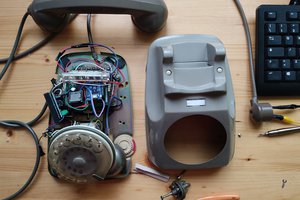
Before Start the project : I recommend to test all of your dial phone's components.
Here is the dial phone components' list that you must test :
-Rotary encoder
-Speaker and microphone
-Solenoid(Ringing system)
If you sure that all of these components works, you can skip the Test step.
Test Instructions :
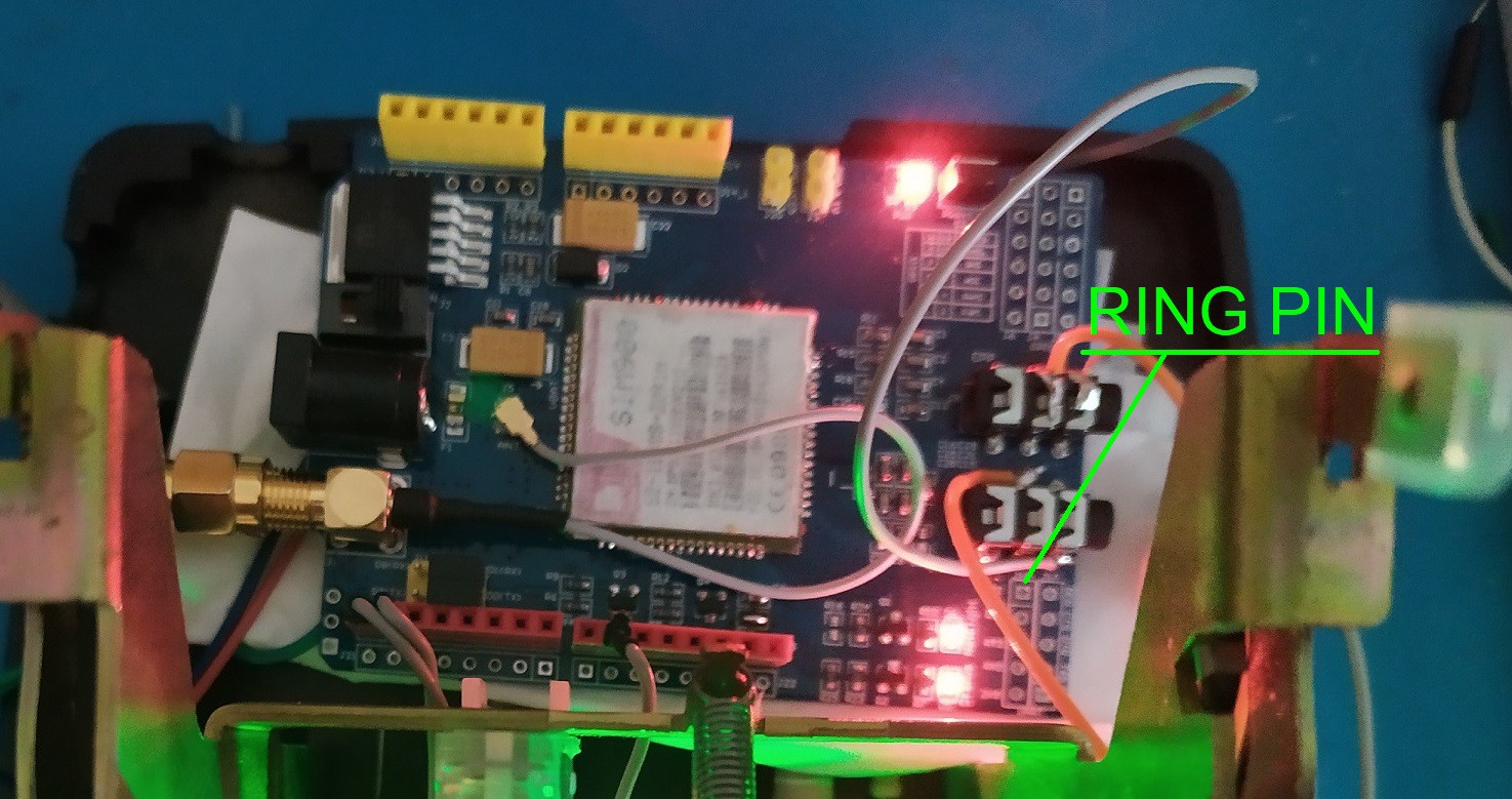
SOLENOID
To understand how to control solenoid. It's works at ±50V(reverse polarity for each ringing pulse) normally. But It can be a problem for us to make a mobile phone.(Understand that you must have around 12 cells "at fully charge", so 4.2v * 12 = 50.4v). And of course, we will not use 12 cells to power the phone(for 1 component !!!), so I tried in lower voltages, and get some results around 7.6 volts(Eurêka !). 2 cells (8.4v "at fully charge") will be enough to get soft ringing.
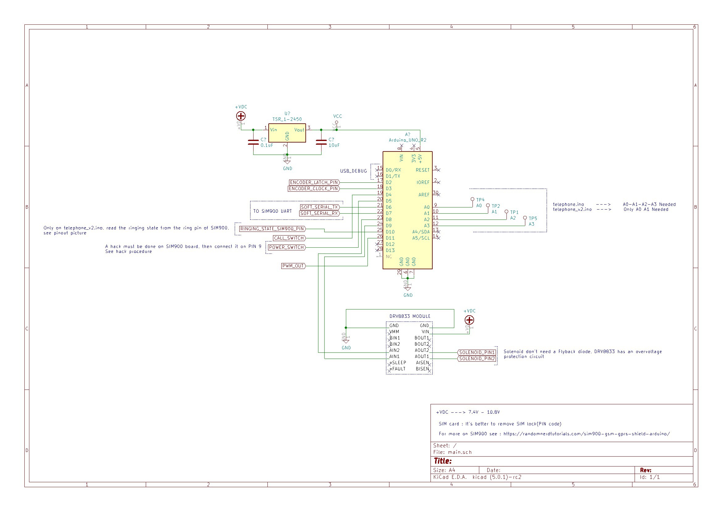
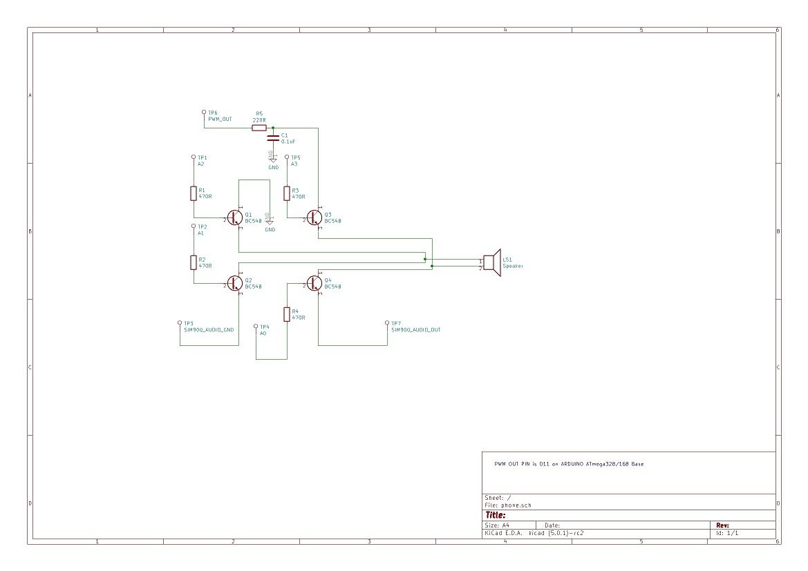
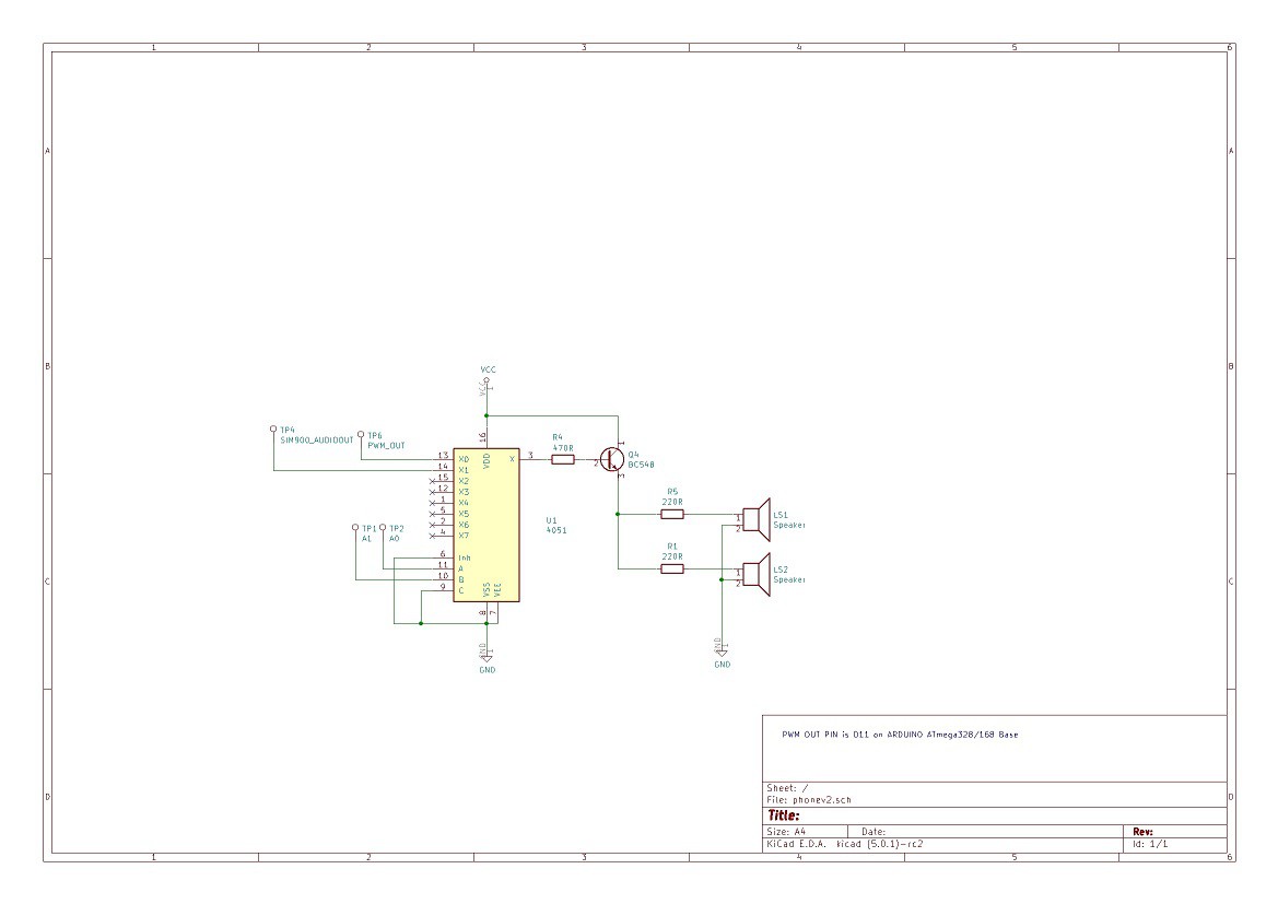
To test the solenoid, just do the wiring like in schematic below :

(Note : The DRV8833 has the overvoltage/overcurrent protection, so a flyback diode is not necessary)
And in your arduino send this sketch :
//DRV8833 Solenoid tester

//PINS definitions
#define D0 2
#define D1 3

//Set a period of TIME_PULSE_BASE * 2 ms
#define TIME_PULSE_BASE 50 //in ms

void setup(){

pinMode(D0, OUTPUT);
pinMode(D1, OUTPUT);

}

void loop(){

digitalWrite(D0,LOW);
digitalWrite(D1,HIGH);
delay(TIME_PULSE_BASE);
digitalWrite(D0,HIGH);
digitalWrite(D1,LOW);
delay(TIME_PULSE_BASE);

}
And you must have this result :
Got this result ? Congrats !!!
Otherwise :
-Check your hardware(If DRV8833 is powered correctly, or If the ground pin is well connected between DRV8833 and arduino, If DRV8833 work as well)
-Change TIME_PULSE_BASE value
-Check your Solenoid
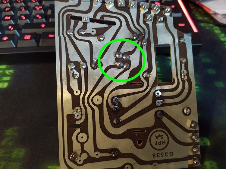
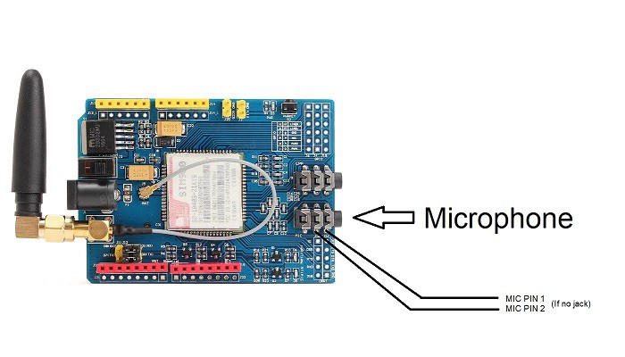
Speaker and microphone
The easiest part :D
For the speaker you can check first the impedance I had around 6~8ohms. But If you want more, you can use an audio source. I used my function generator to test it.
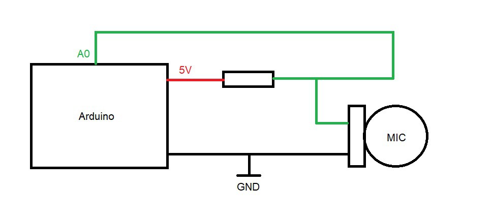
For the microphone, like the speaker you can check the impedance(be aware that the value will vary according to the sound), otherwise you can make a voltage divider between a 10K resistor and you microphone and wire it to the arduino.
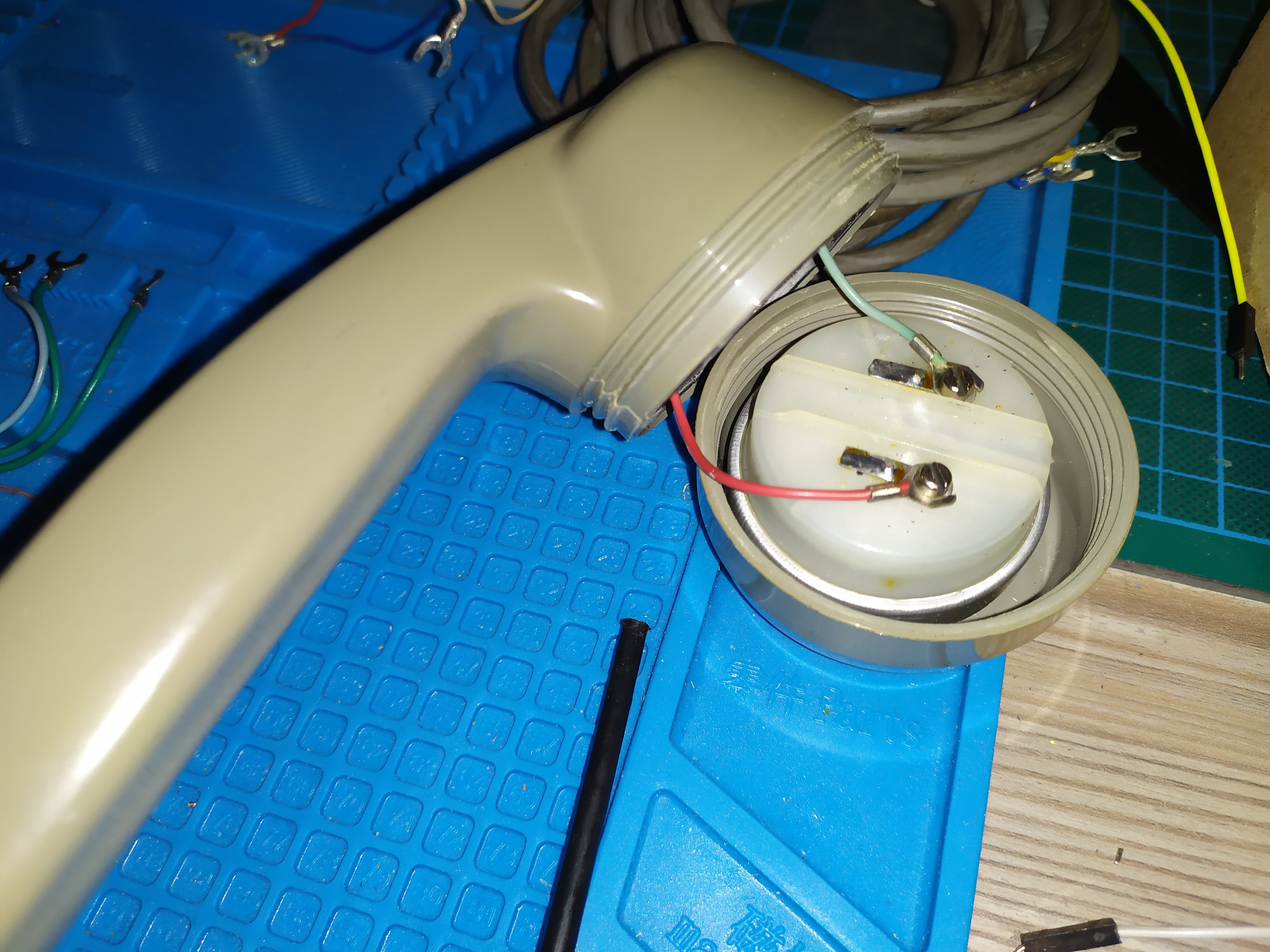
Note : If you don't know which wire correspond of each components, well you open handset's caps and you'll get your answer.
Next, in the arduino you can upload this sketch
//Microphone Tester Sketch

#define MIC_PIN A0

void setup(){

//Just need this
Serial.begin(115200);

}

void loop(){

Serial.println(analogRead(MIC_PIN));
delay(50);

}
And you can open the Serial Monitor/Plotter to check you signal, you might get the same result like below(otherwise check you wiring or microhpone).
Rotary Encoder
The encoder, has 4 pins :
-A common pin
-A clock pin
-2 latch pins
How it works ?
When you start to dial(turn the encoder in counter-clockwise), Latch pins goes switch to the common pin level. When you leave the encoder, it goes to turn in clockwise and the clock pin will pulse at the same number of time as the number dialed. (Ex : Number 3 dialed = 3 pulses)
To test it, find the correspond wires, and do this wiring :
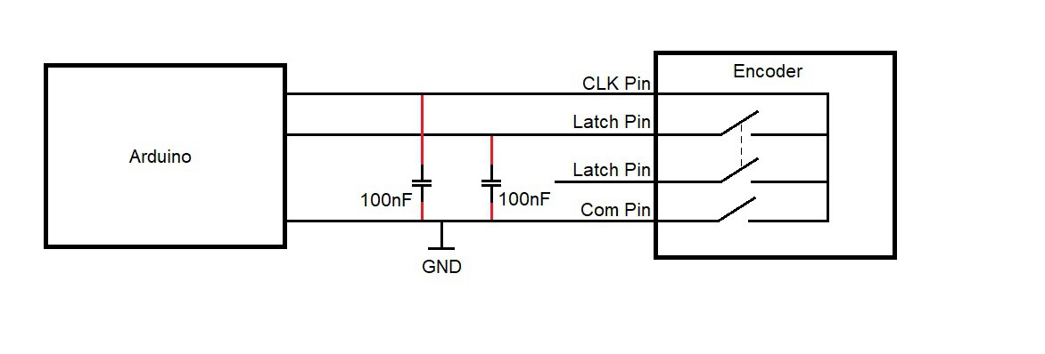
And upload this sketch :
//Encoder Tester Sketch

#define LATCH  2
#define CLOCK  3


void setup(){

//Init serial port
Serial.begin(115200);

//set pullup pins
pinMode(LATCH, INPUT_PULLUP);
pinMode(CLOCK, INPUT_PULLUP);

}


void loop(){

Serial.print(digitalRead(CLOCK));
Serial.print("\t");
Serial.println(digitalRead(LATCH));
delay(50);

}
You might get this result :


If all of your components works well, congrats ! You're ready to start the build of your future mobile phone !


 Saabman
 Rob Englebright
 Giulio Pons
Hi! I'm trying to build the telephone. So far, a part from changing the driver for the solenoid and choosing a higher voltage, everything seems to be ok. However, nowadays 2G/3G networks are being shut down. Has anyone tried it with something more modern than a SIM900 or a SIM800L?