 kutluhan_aktar
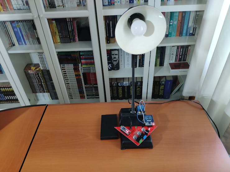
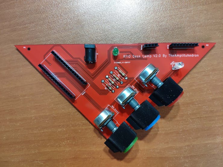
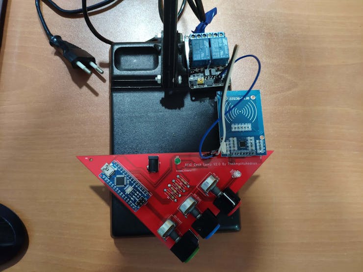
After completing my project, I designed the mentioned PCB with the unique triangular shape complementary to the lamp.
Huge thanks to JLCPCB for sponsoring this project.
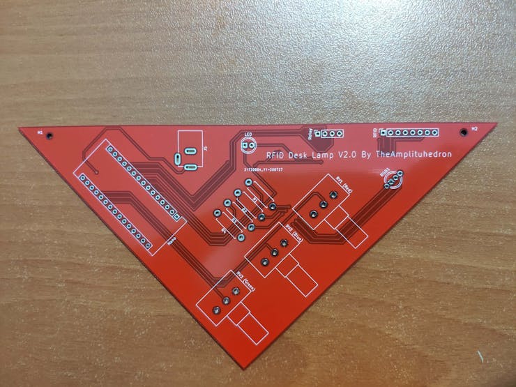
Step 1: Designing and Soldering the RFID Desk Lamp v2.0 PCB
I designed the RFID Desk Lamp v2.0 PCB by using KiCad. I attached the Gerber file of the PCB below, so if you want, you can order this PCB from JLCPCB to renew your older lamps as I did :)
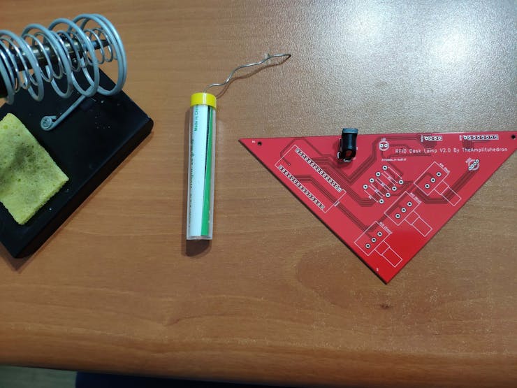
First of all, by using a soldering iron, I attached headers, resistors, the power jack, RGB, 5mm green LED, and potentiometers.
Component list on the PCB:
Nano (Headers for Arduino Nano)
RFID (Headers for MFRC522 RFID Module)
Relay (Headers for 2-Way Relay)
RGB1 (RGB)
LED (5mm Green LED)
J5 (Power Jack)
R1, R2, R3, R4 (220Ω Resistors)
RV1 (Red Pot.)
RV2 (Blue Pot.)
RV3 (Green Pot.)
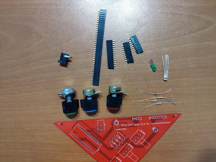
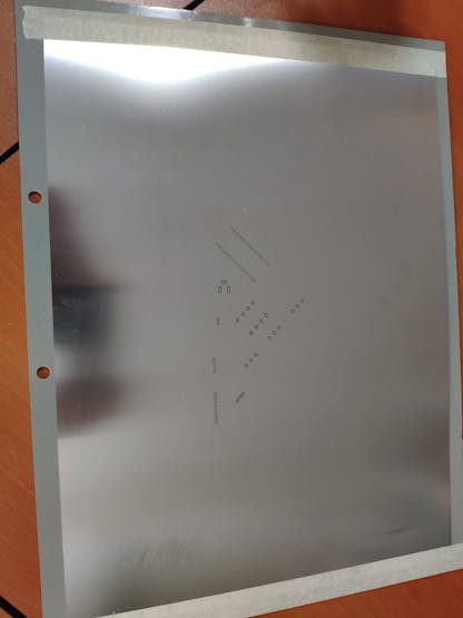
Even though there are no SMD components on the board, if you want, you can order a stencil to apply solder paste to the holes as I did, especially for soldering a headerless Arduino Nano.
Step 2: Registering and Reading UIDs with the MFRC522 RFID Module
Download the required library for the MFRC522 RFID Module from here.
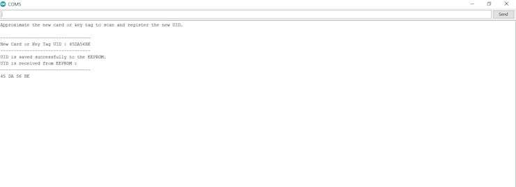
Not surprisingly, it is simple to register and read UIDs with the MFRC522 RFID Module: approximate the RFID card or key to the module and run the code for reading or registering.
To save a new UID to the EEPROM, uncomment the registerCardUID() function and run the code:
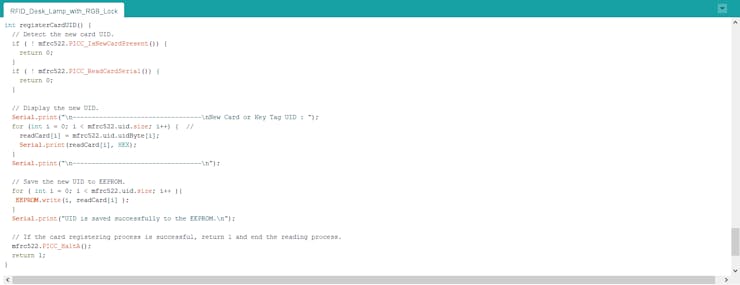
int registerCardUID() {  // Detect the new card UID.   if ( ! mfrc522.PICC_IsNewCardPresent()) {     return 0;  }  if ( ! mfrc522.PICC_ReadCardSerial()) {    return 0;  }
  // Display the new UID.  Serial.print("\n----------------------------------\nNew Card or Key Tag UID : ");  for (int i = 0; i < mfrc522.uid.size; i++) {  //    readCard[i] = mfrc522.uid.uidByte[i];    Serial.print(readCard[i], HEX);  }  Serial.print("\n----------------------------------\n");    // Save the new UID to EEPROM.   for ( int i = 0; i < mfrc522.uid.size; i++ ){   EEPROM.write(i, readCard[i] );  }  Serial.print("UID is saved successfully to the EEPROM.\n");    // If the card registering process is successful, return 1 and end the reading process.  mfrc522.PICC_HaltA();  return 1;
}
To get the saved UID in the EEPROM, run this code:
int get_saved_UID(){  // Get the saved UID in the EEPROM.  for(int i=0;i<4;i++){    savedUID += EEPROM.read(i) < 0x10 ? " 0" : " ";    savedUID += String(EEPROM.read(i), HEX);    }  // Arrange the savedUID for comparison.  savedUID.trim();  savedUID.toUpperCase();
}
To compare the saved UID in the EEPROM and the currently read UID by the RFID module, execute this code:
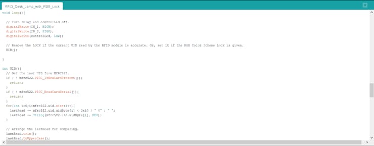
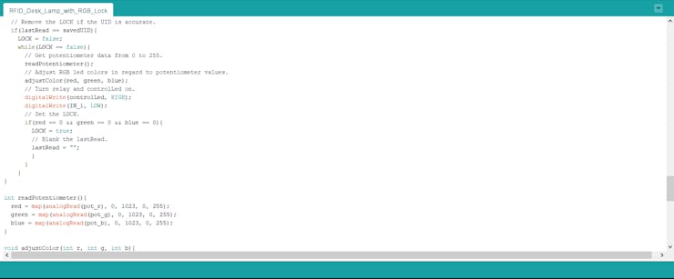
int UID(){  // Get the last UID from MFRC522.  if ( ! mfrc522.PICC_IsNewCardPresent()){    return;  }  if ( ! mfrc522.PICC_ReadCardSerial()){    return;  }  for(int i=0;i<mfrc522.uid.size;i++){    lastRead += mfrc522.uid.uidByte[i] < 0x10 ? " 0" : " ";    lastRead += String(mfrc522.uid.uidByte[i], HEX);  }    // Arrange the lastRead for comparison.  lastRead.trim();  lastRead.toUpperCase();
    // Remove the LOCK if the UID is accurate.  if(lastRead == savedUID){    LOCK = false;    while(LOCK == false){      // Get potentiometer data from 0 to 255.      readPotentiometer();      // Adjust RGB led colors in regard to potentiometer values.      adjustColor(red, green, blue);      // Turn relay and controlLed on.      digitalWrite(controlLed, HIGH);      digitalWrite(IN_1, LOW);      // Set the LOCK.      if(red == 0 && green == 0 && blue == 0){        LOCK = true;        // Blank the lastRead.        lastRead = "";        }      }    }
}
For more detailed information about the code, please go to the following step.
Step 3: Programming the Arduino Nano
- Include the required libraries.
- Create the MFRC522 instance.
- Define the MFRC522 module key input.
- Define the readCard byte array storing the scanned ID read by RFID Module.
- Define the data holders.
- Define the LOCK boolean to either set or remove the LOCK.
- Define RGB pins, the controlLed pin, and potentiometer pins.
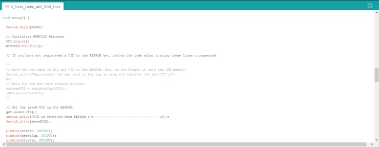
- Initialize MFRC522 Hardware.
- If you have not registered a UID to the EEPROM yet, upload the code after turning the emphasized lines uncommented.
- In the registerCardUID() function:
- Detect the new card UID.
- Save the new UID to the EEPROM.
- If the card registering process is successful, return 1 and end the reading process.
- In the get_saved_UID() function:
- Get the saved UID in the EEPROM.
- Arrange the savedUID for comparison.
- In the UID() function:
- Get the currently read UID by the MFRC522.
- Arrange the lastRead for comparing.
- Remove the LOCK if the UID is accurate.
- Get potentiometer data from 0 to 255.
- Adjust RGB colors in regard to potentiometer values.
- Turn on the relay and the controlLed.
- Set the LOCK if the RGB color scheme (0, 0, 0) is given.
- Blank the lastRead.
Connections and Adjustments
// Connections
// Arduino Nano :           //                            MFRC522
// D9  ----------------------- RST
// D10 ----------------------- SDA
// D11 ----------------------- MOSI
// D12 ----------------------- MISO
// D13 ----------------------- SCK
//                            5mm Green LED (controlLed)
// D2  -----------------------
//                            RGB
// D3  -----------------------
// D6  -----------------------
// D5  -----------------------
//                            2-Way Relay
// D7  ----------------------- IN_2
// D8  ----------------------- IN_1
//                            Potentiometer (Red)
// A0 -----------------------
//                            Potentiometer (Green)
// A1 -----------------------
//                            Potentiometer (Blue)
// A2 -----------------------
After finishing and uploading the code to the Arduino, I attached the remaining components to the board through headers.
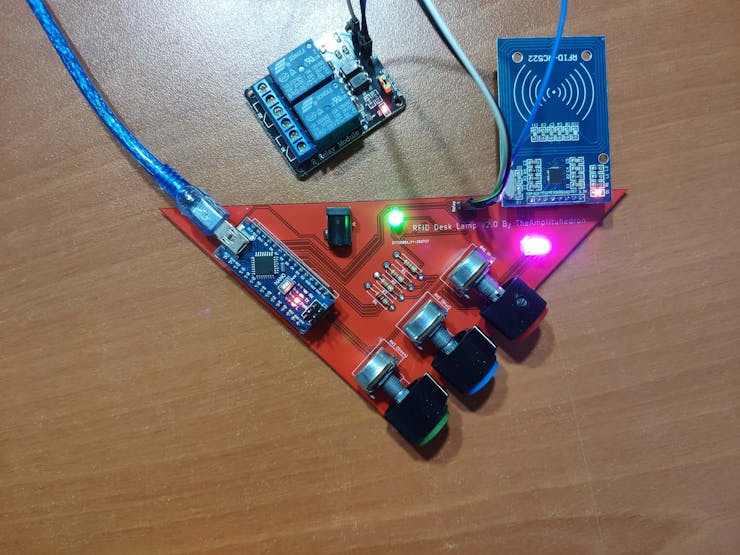
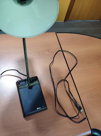
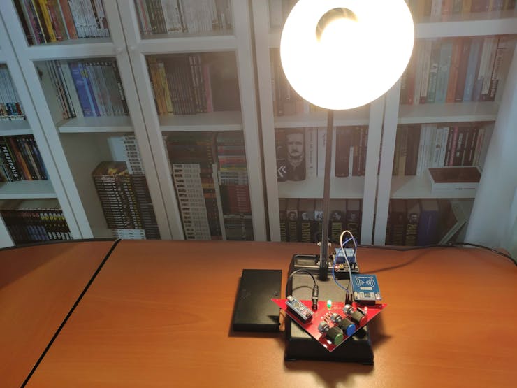
Then, I fastened the PCB to my lamp by using a hot glue gun and connected its cable to the 2-Way relay to control the light.
Features
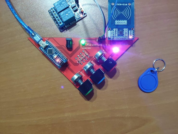
1) Save a new RFID card or tag to the EEPROM to use it to remove the lock.
2) To remove the lock, and be able to adjust the RGB color pattern, approximate the registered RFID card or tag to the MFRC522 RFID Module.
The controlLed (5mm Green LED) turns on when the lock is removed.
3) For activating the lock, apply the selected RGB color scheme. In this version - the pattern is 0, 0, 0 - you have to reduce all potentiometer values to zero (black). But, if you want to use a different pattern, you can change it in the UID() function.
The controlLed (5mm Green LED) turns off when the lock is set.
Note: You cannot adjust the RGB color pattern - turns off - while locked.
