 Subhajit
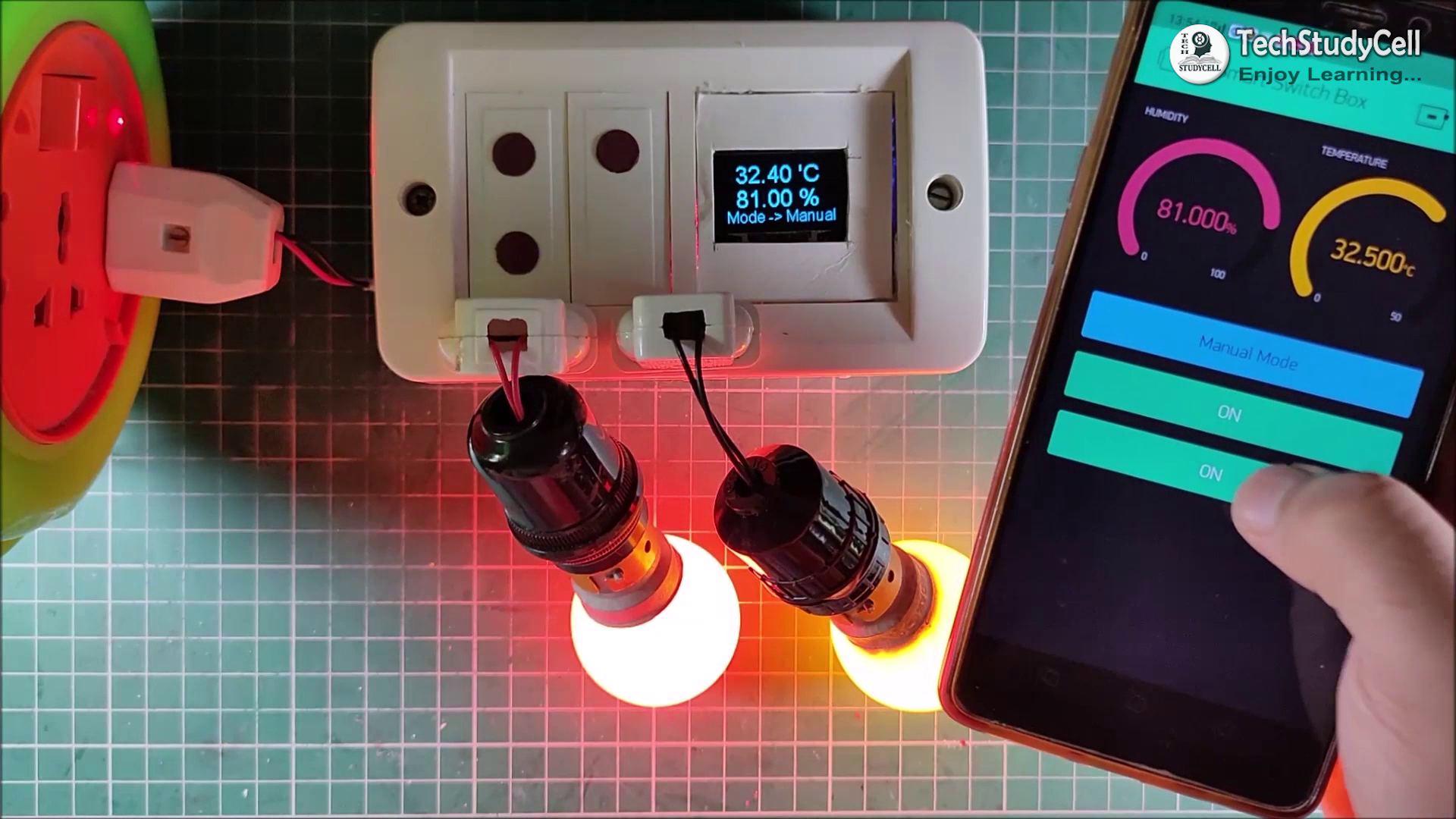
This smart home project has the following features:
1. Home appliances controlled from Mobile using Blynk App
2. Home appliances controlled by temperature & Humidity sensor automatically (In Auto Mode)
3. Home appliances controlled by Dark Sensor automatically (In Auto Mode)
4. Monitor LIVE room temperature & Humidity reading on OLED and Smartphone
5. Home appliances controlled manually with touch switch
6. Control Home appliances through the Internet (WiFi)
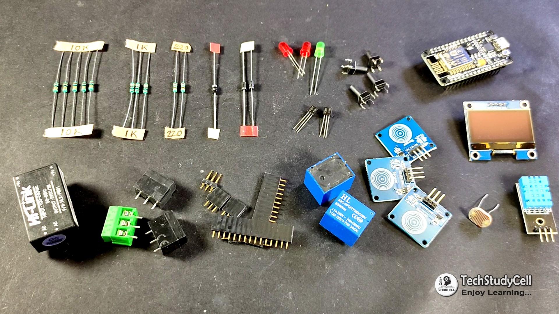
Supplies:
1. NodeMCU Board
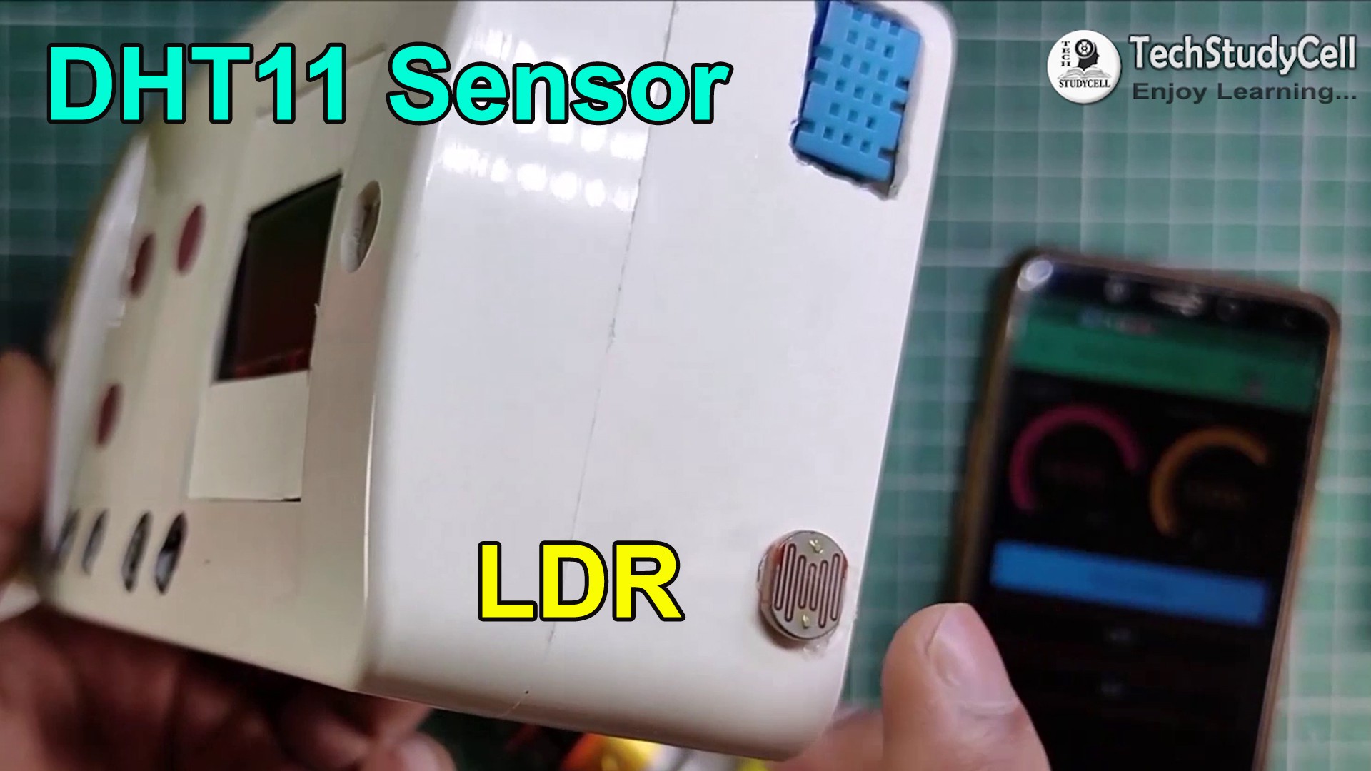
2. DH11 Sensor
3. LDR
4. 10k Resistors 5 no
5. 1k Resistors 3 no
6. 220-ohm Resistors 2 no
7. BC547 NPN Transistors 2 no
8. Diode 1N4007 2 no
9. Diode 1N4001 1no
10. 5-mm LED (1.5v) 3 no
11. SPDT 5V Relays 2 no
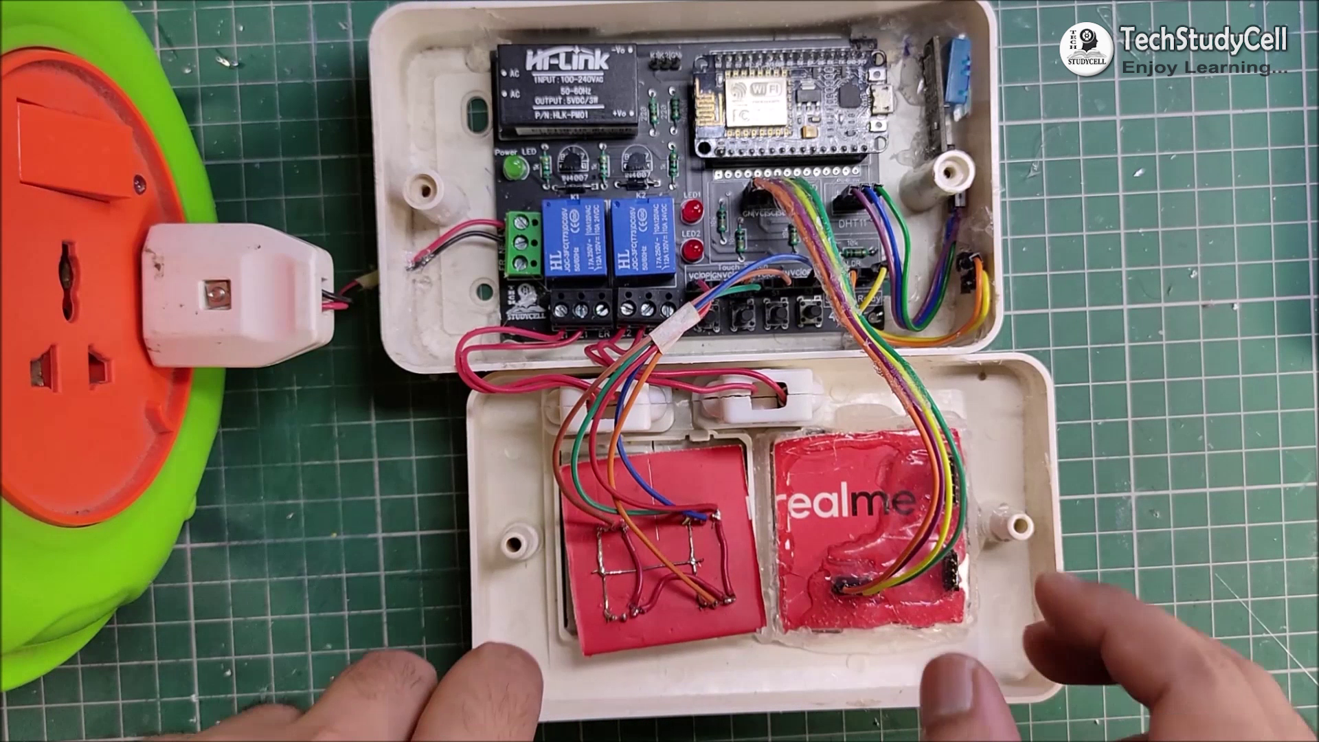
12. Push Switch/ button 4 no (or) TTP223 Touch Sensor (3no)
13. Connectors & jumpers
14. OLED I2C Display (0.96" or 1.3") (Optional)
15. Hi-Link 220V to 5V AC to DC converter
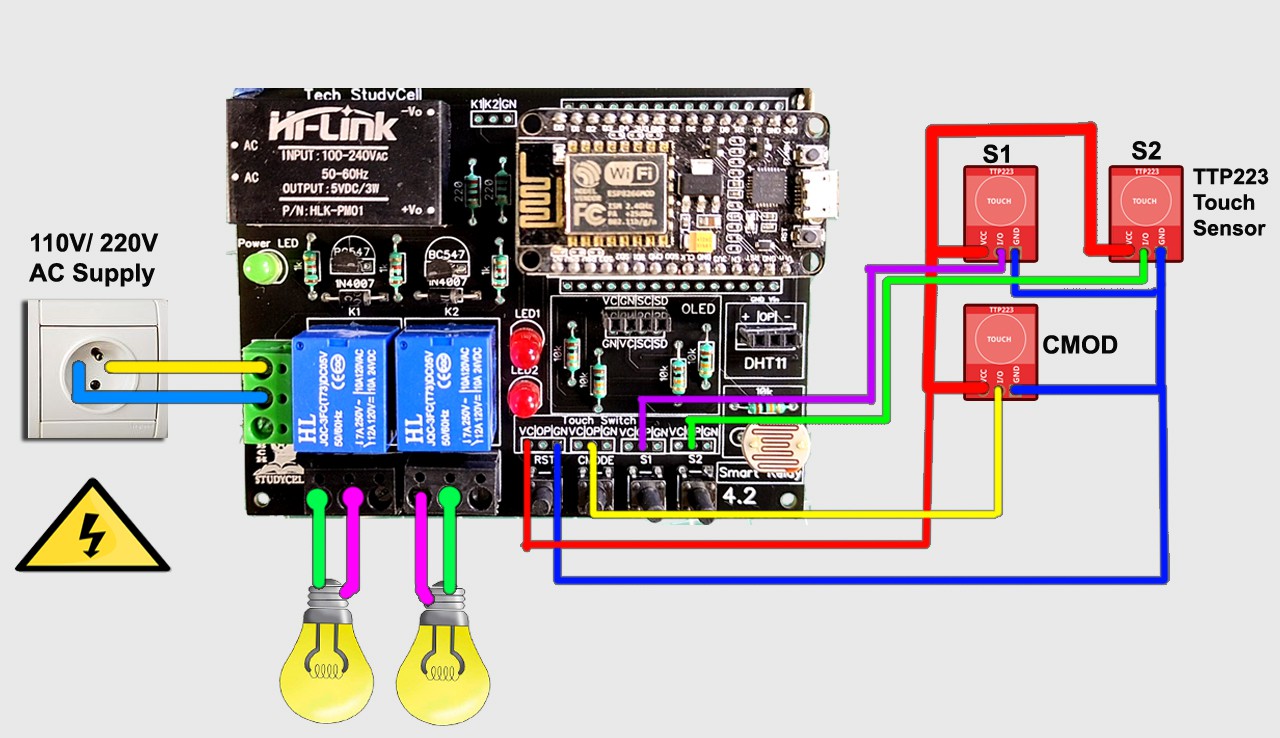
Circuit Diagram
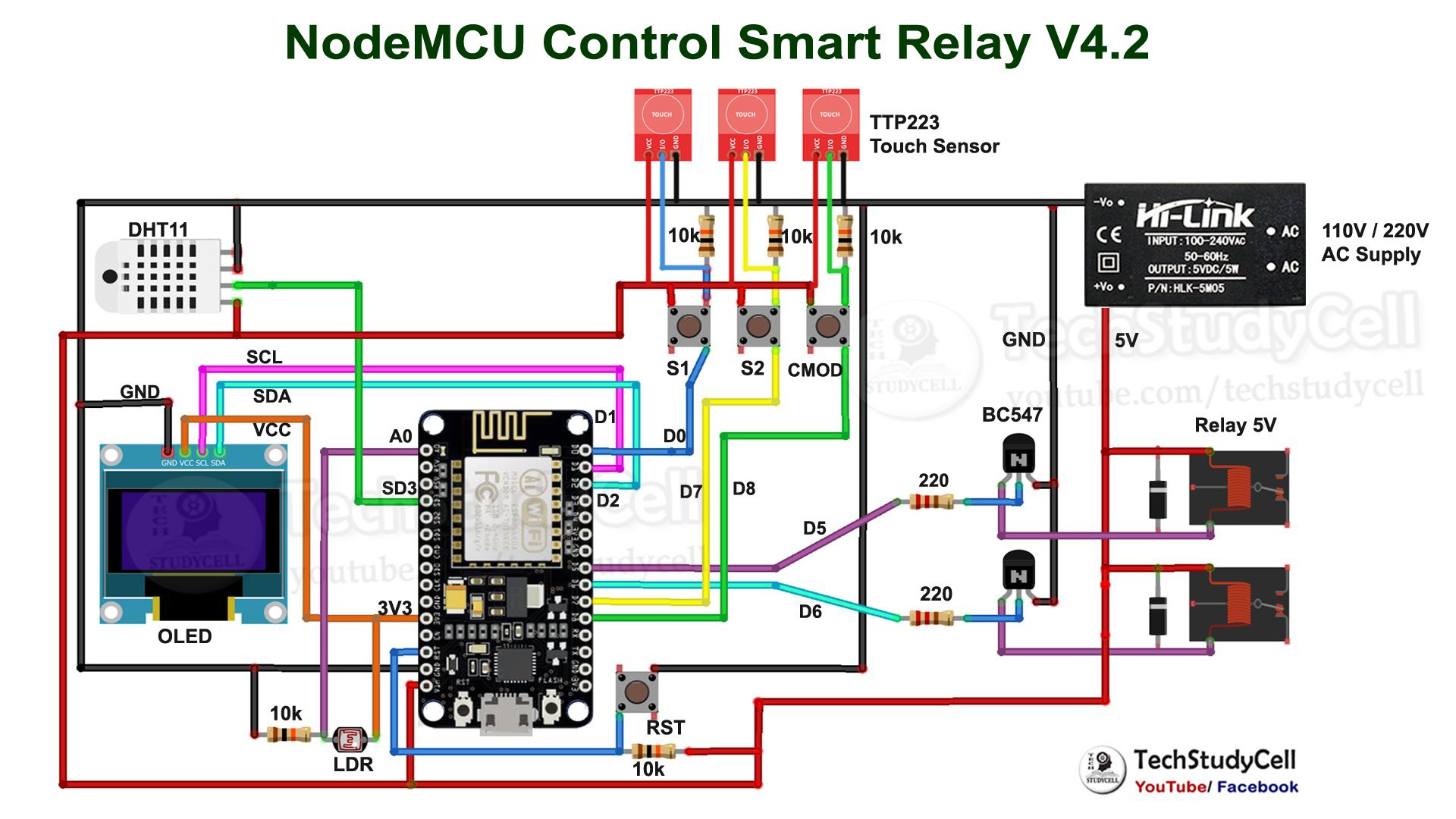
This is the complete circuit diagram for this IoT based smart home system.
I have used NodeMCU to control the relay module. I have connected the DHT11 temperature & humidity sensor and LDR to control the relay automatically according to the room temperature and ambient light.
There four pushbuttons connected with NodeMCU i.e, S1, S2, CMODE, RST.
S1 & S2 to control the relay module manually.
You can also connect the TTP223 Touch sensors instead of pushbuttons.
CMODE to change the Mode (Manual Mode, Auto Mode)
RST to reset the NodeMCU
I have used a 110V/220V AC to 5V DC converter to supply the 5V to NodeMCU and relays.
So you can connect directly 110V or 220V AC supply with this smart relay module.
Make the Circuit on Breadboard for Testing
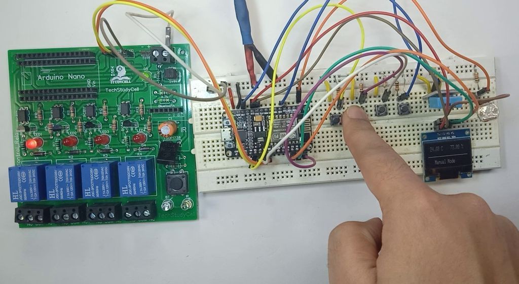
Before designing the PCB, first I have made the circuit on the breadboard for testing.
During testing, I have uploaded the code to the NodeMCU then tried to control the relays with the pushbuttons, touch switch. Blynk App, temperature sensor, and LDR.
Here RST pin is active low, so the Touch sensor connected with the RST pin should be active low.
Download the Code for this NodeMCU project
https://drive.google.com/uc?export=download&id=1YYNdAP82RXpnSHdcrL4j59f_t97e-JEY
I have mentioned all the download links for the required Arduino libraries in the code.
Tutorial Video for This IOT Project:
In the tutorial video, I have explained all the steps for making this Smart Home device in detail.
So you can easily make this IoT project for your home.
Install the Blynk App:
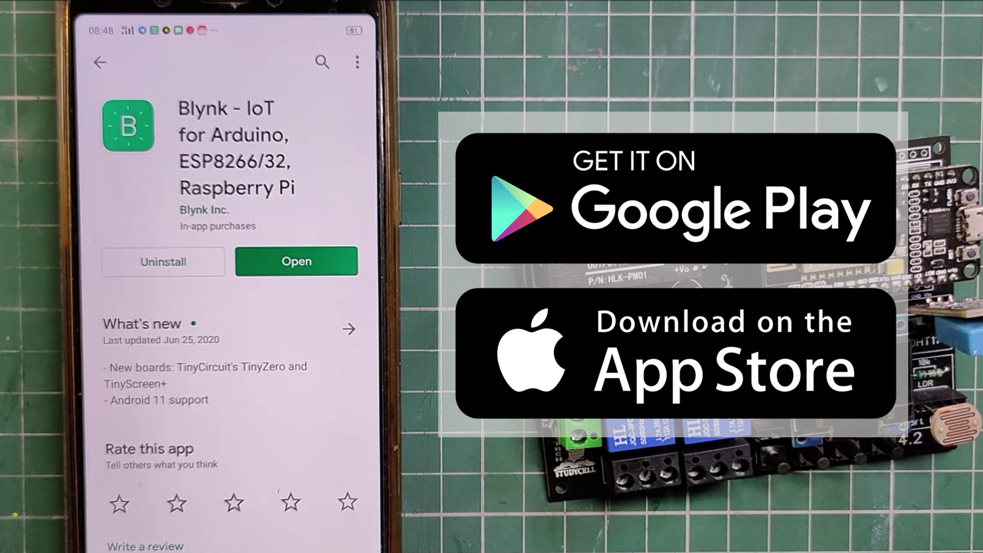
Install the Blynk App from Google play store or App store then add all the required widgets to control the relay module and monitor the temperature and humidity. I have explained all the details in the tutorial video.
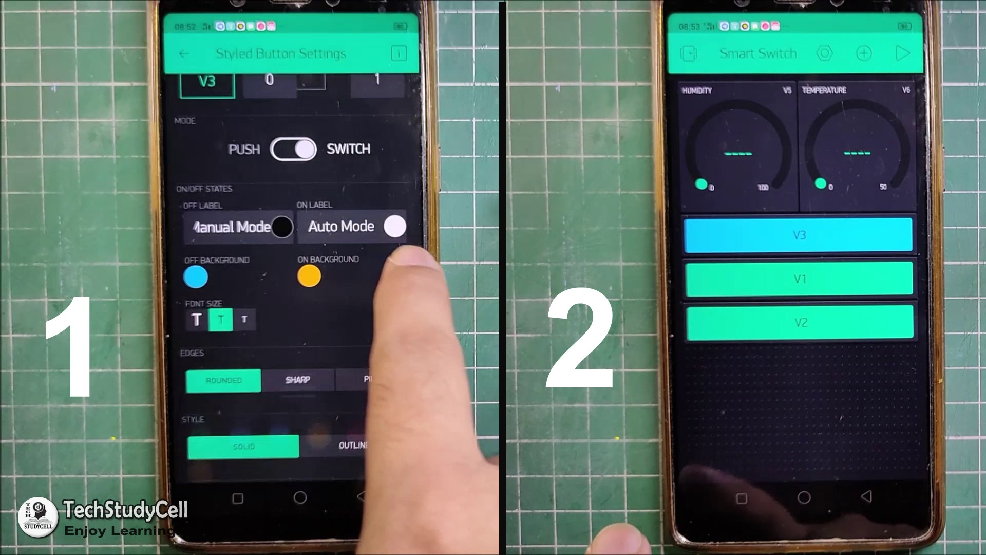
I have used the 3 button widgets to control the relay module and change the mode.
And 2 gauge widgets to monitor the temperature and humidity.
Different Mode of the Smart Relay Module:
We can control the smart relay in two modes:
1. Manual Mode
2. Auto Mode
We can easily change the mode with the CMODE button fitted on the PCB or from the Blynk App.
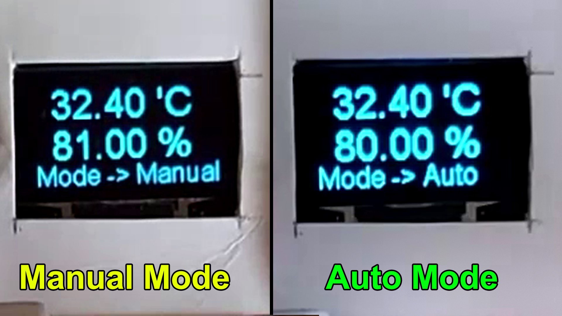
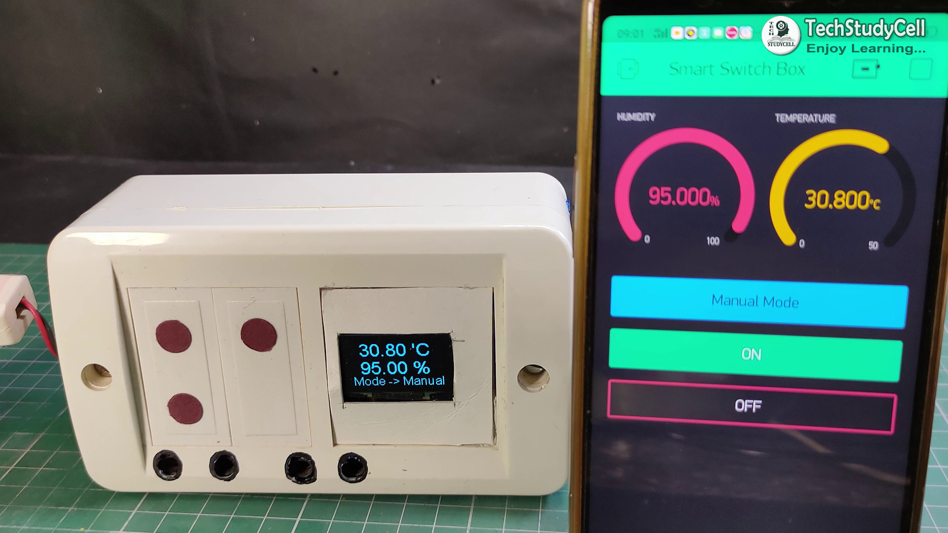
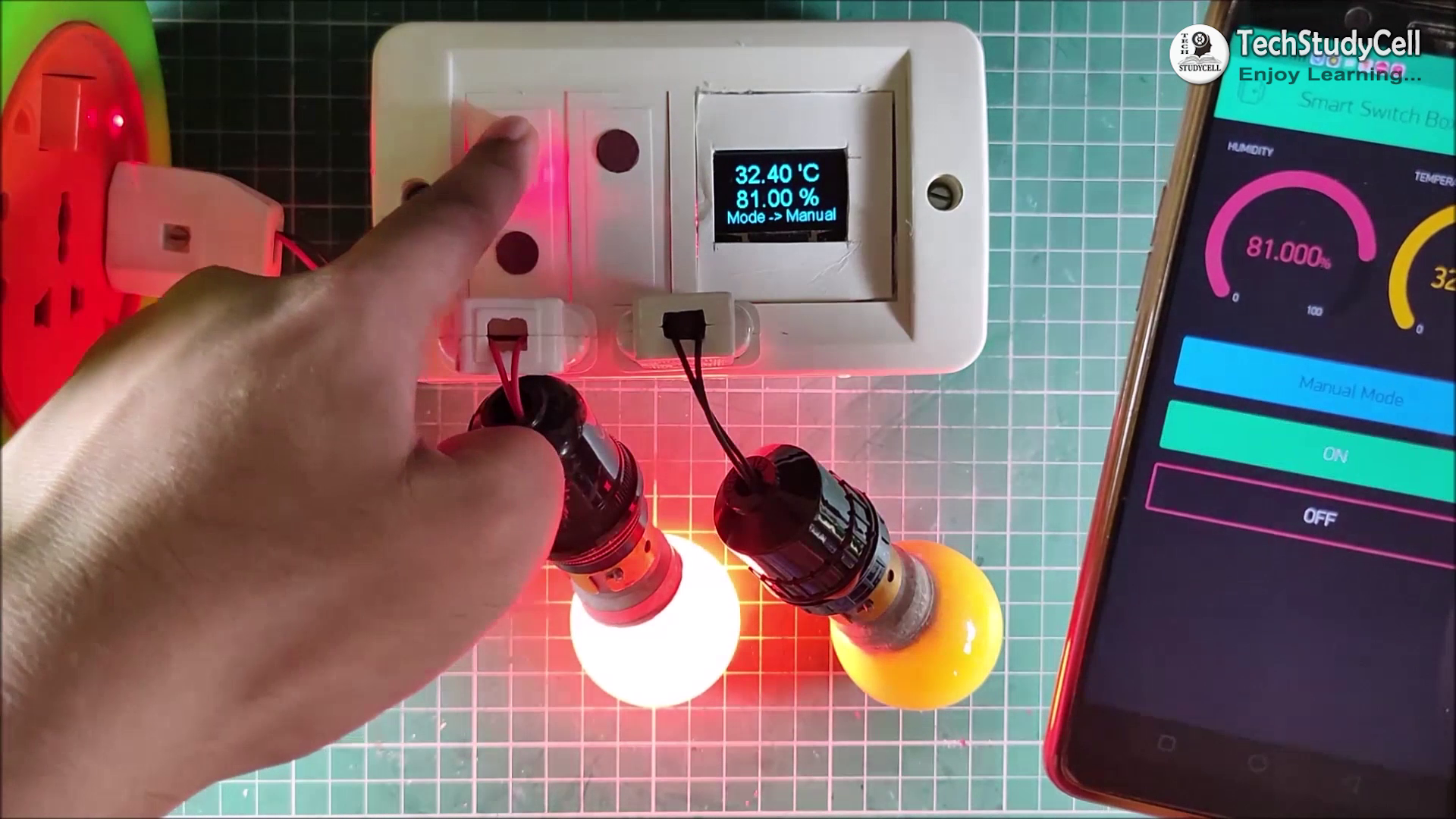
Manual Mode:
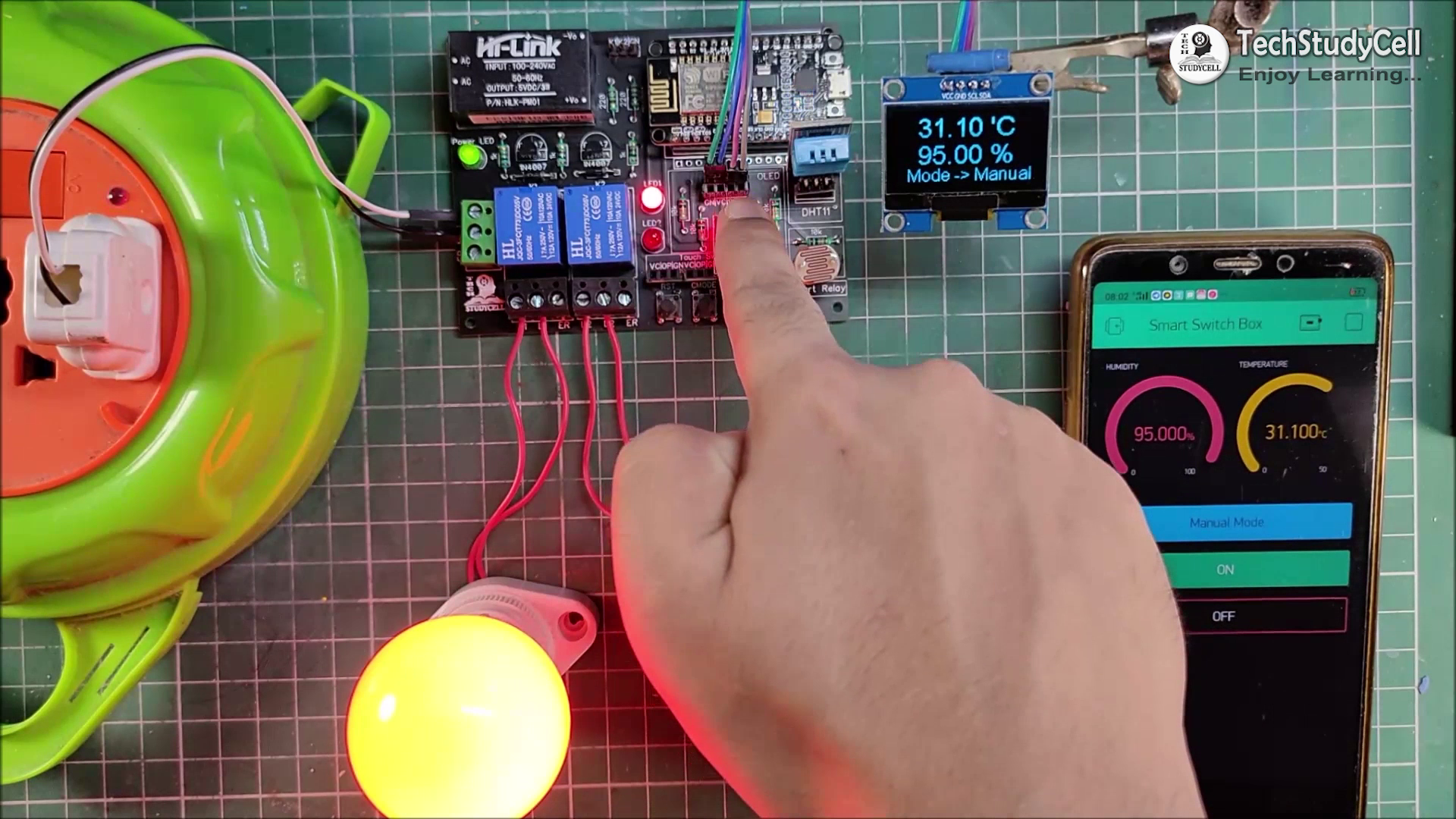
In the Manual mode, we can control the relay module from the S1 & S2 touch switches or from the Blynk App.
We can always monitor the real-time feedback status of the switches from the Blynk App
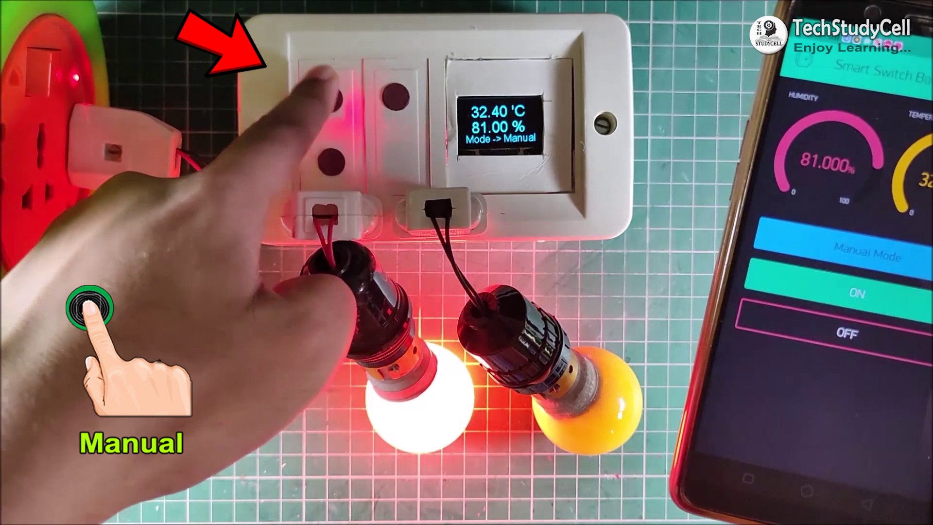
And we can also monitor the temperature and humidity reading on the OLED display and the Blynk App as you can see in the pictures.
With the Blynk App, we can control the relay module from anywhere if we have the internet on our smartphone.
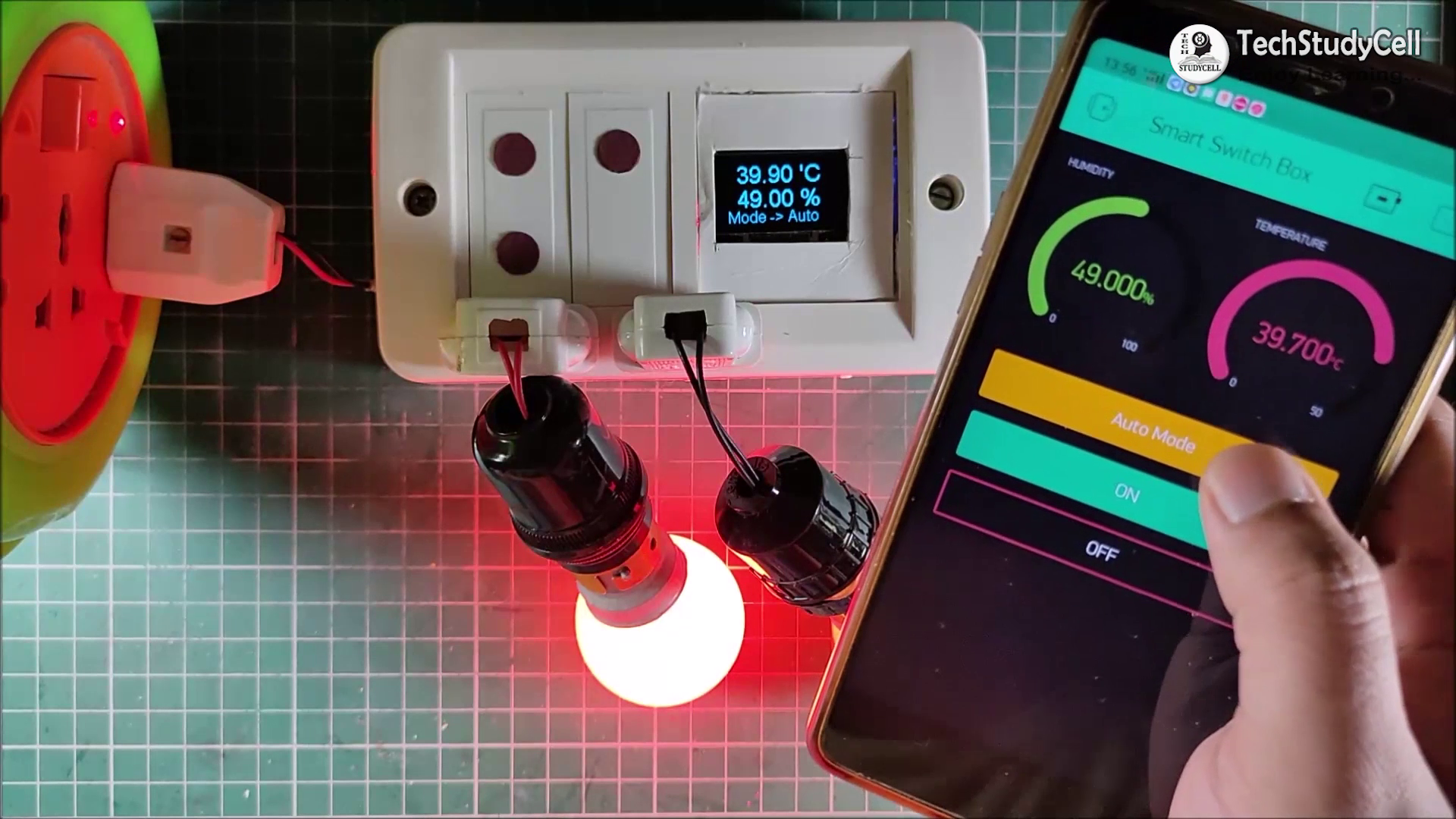
Auto Mode:
In Auto mode, the relay module controlled by the DHT11 sensor and LDR.
We can set a predefined minimum and maximum temperature and light values in the code.
Temperature Control
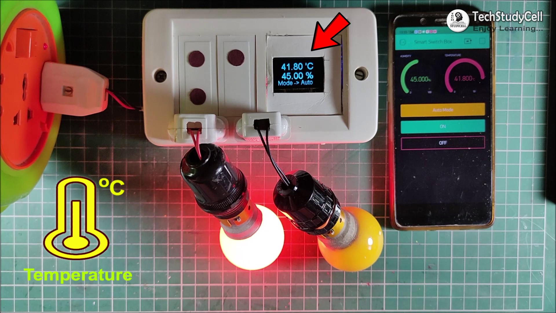
When the room temperature crosses the predefined maximum temperature the relay-1 turns on and when the room temperature becomes lesser than the predefined minimum temperature the relay-1 turns off automatically.
LDR Control
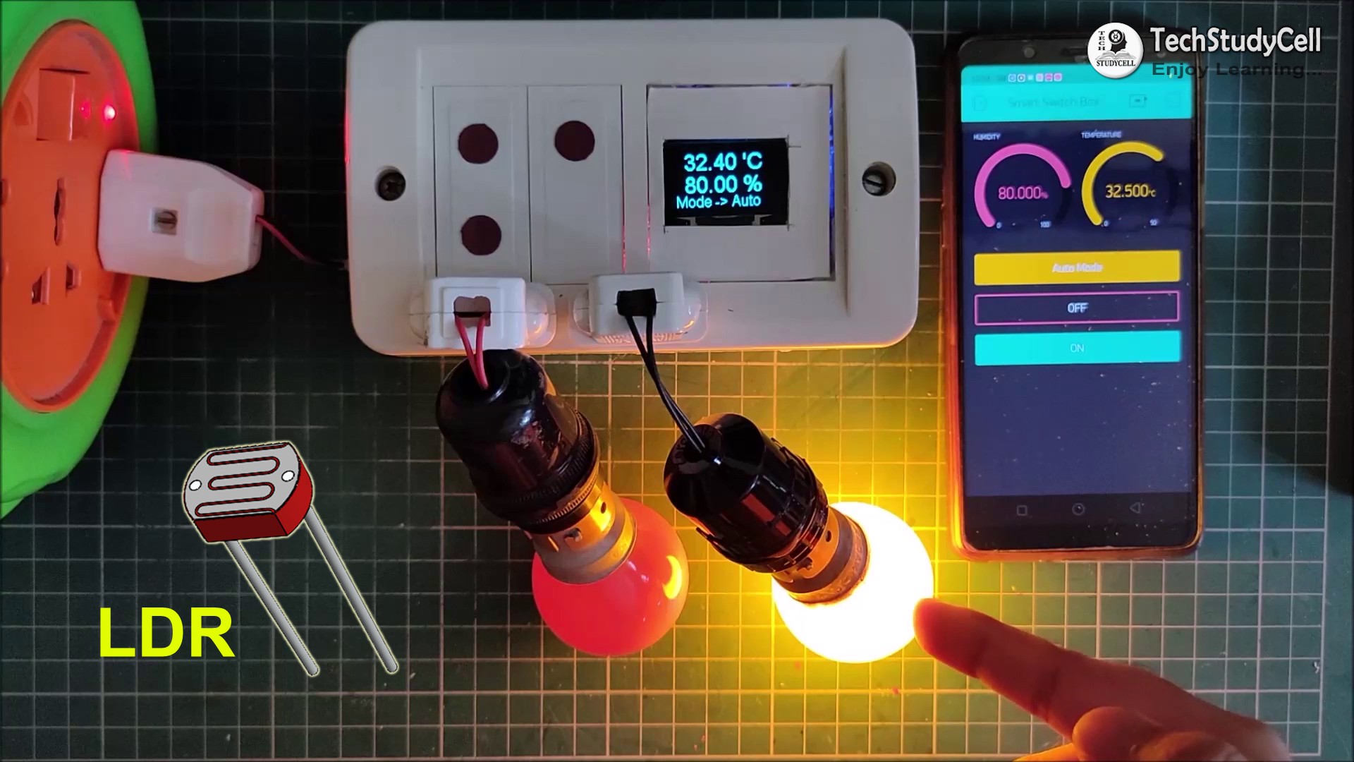
In a similar way when the light level decreases the relay-2 turns on and when the light is sufficient the relay-2 turns off automatically.
I have explained in details in the tutorial video.
Designing the PCB:
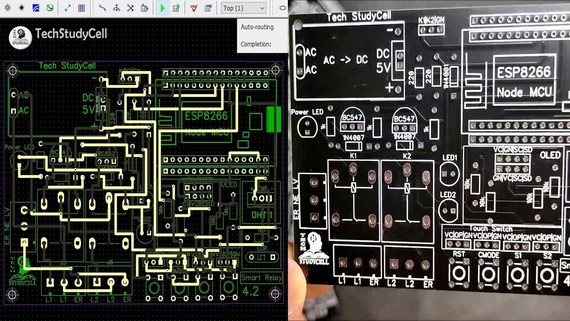
After testing all the features of the smart relay module on the breadboard, I have designed the PCB to make the circuit compact and give the project a professional look.
You can download the PCB Gerber file of this IoT based home automation project from the following link:
https://drive.google.com/uc?export=download&id=1EJY744U5df6GYXU8PtyAKucyPrD-gViX
Order the PCB:

After downloading the Garber file you can easily order the PCB
1. Visit https://jlcpcb.com and Sign in / Sign up
2. Click on the QUOTE NOW button.
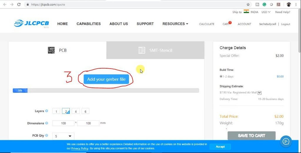
3. Click on the "Add your Gerber file" button. Then browse and select the Gerber file you have downloaded.
Uploading the Gerber File and Set the Parameters:

4. Set the required parameter like quantity, PCB masking color, etc
5. After selecting all the Parameters for PCB click on SAVE TO CART button.

Select Shipping Address and Payment Mode:
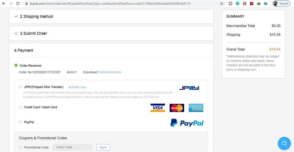
6. Type the Shipping Address.
7. Select the Shipping Method suitable for you.
8. Submit the order and proceed for the payment.
You can also track your order from the JLCPCB.com.
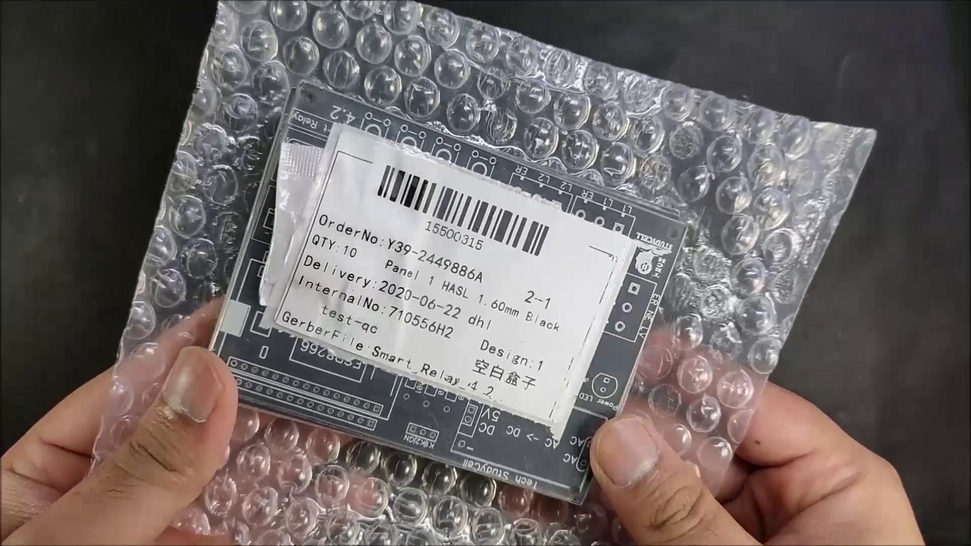
My PCBs took 2 days to get manufactured and arrived within a week using the DHL delivery option.
PCBs were well packed and the quality was really good at this affordable price.
Solder All the Components:
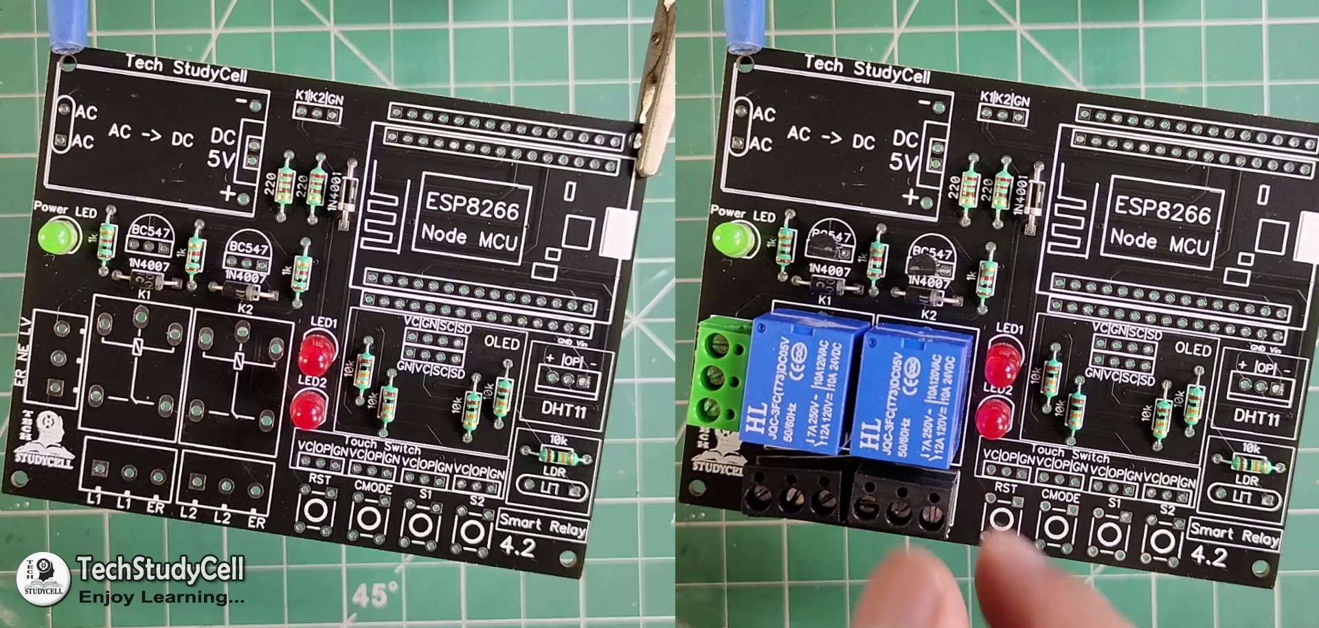
After that solder all the components as per the circuit diagram.
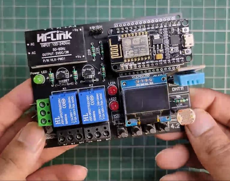
Then connect NodeMCU, DHT11, LDR, and OLED display.
Program the NodeMCU:
1. Connect the NodeMCU with laptop
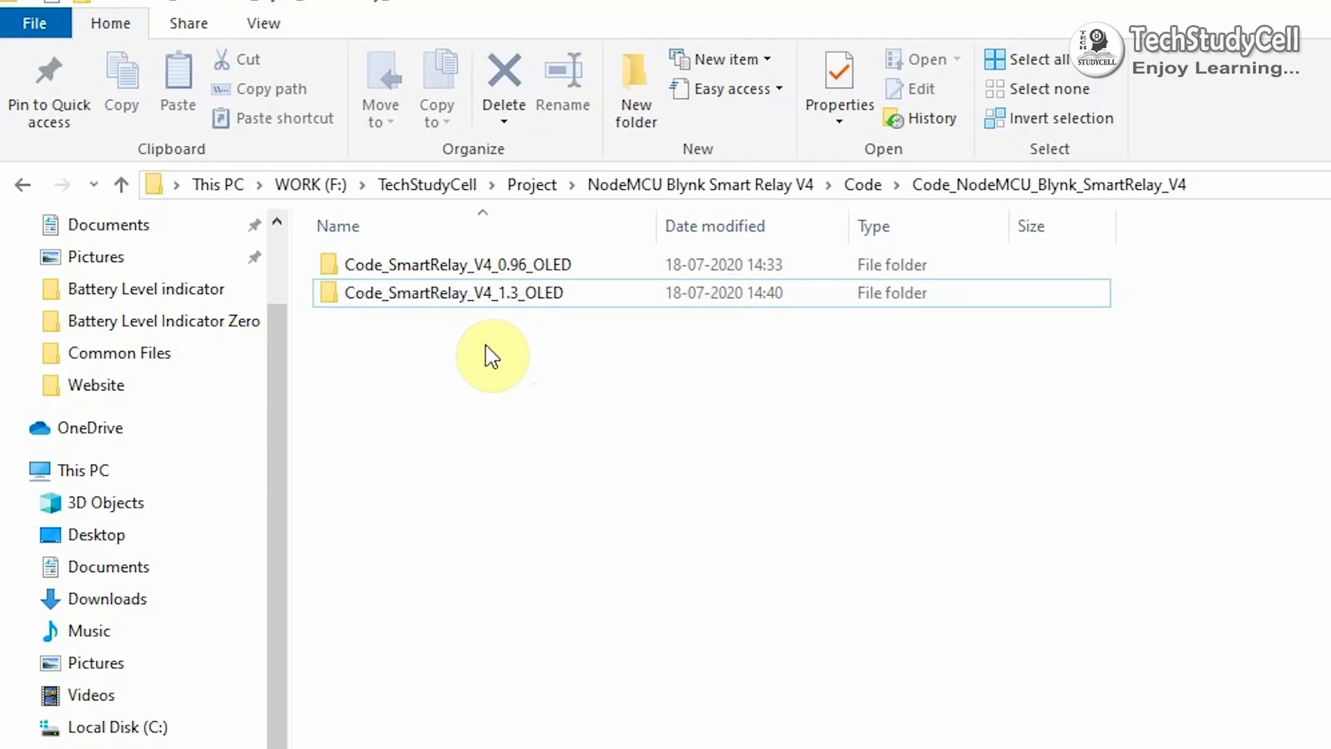
2. Download the Code. (Attached)
Download Link
https://drive.google.com/uc?export=download&id=1YYNdAP82RXpnSHdcrL4j59f_t97e-JEY
I have mentioned all the download links for the required Arduino libraries in the code.

3. Change the Blynk Auth token, WiFi Name, WiFi Password.
4. Change the predefined temperature and light value for Auto Mode as per your requirement
5. Select the NodeMCU 12E board and proper PORT. Then upload the code.
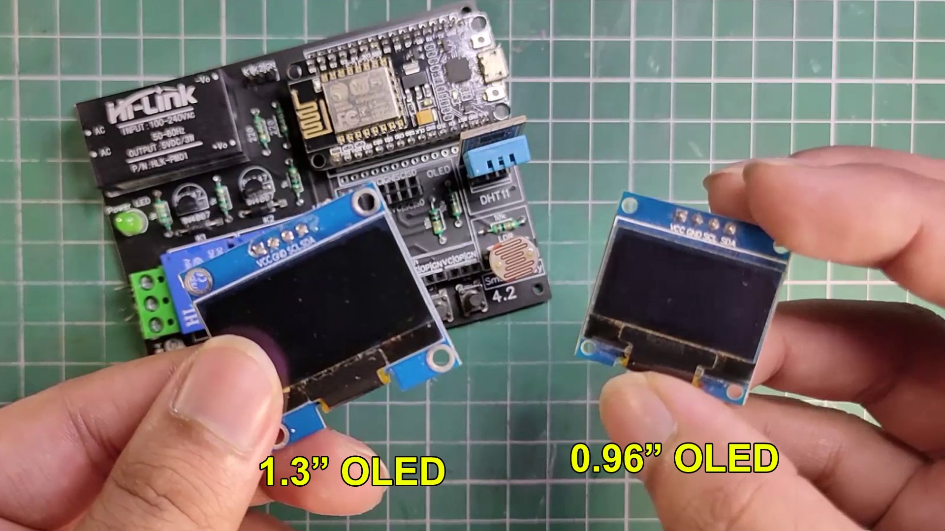
** In this project, you can use both 0.96" OLED and 1.3" OLED display. I have shared the Code for both OLED, upload the code as per the OLED display you are using.
I have already attached the code in the previous steps.
Connect the Home Appliances:
Connect the home appliances as per the circuit diagram.
Please take proper safety precautions while working with high voltage.
Here you can directly connect 110V or 220V AC supply.
** I have not used touch sensor for the RST pin as it is active LOW.
Place the Complete Circuit Inside a BOX:
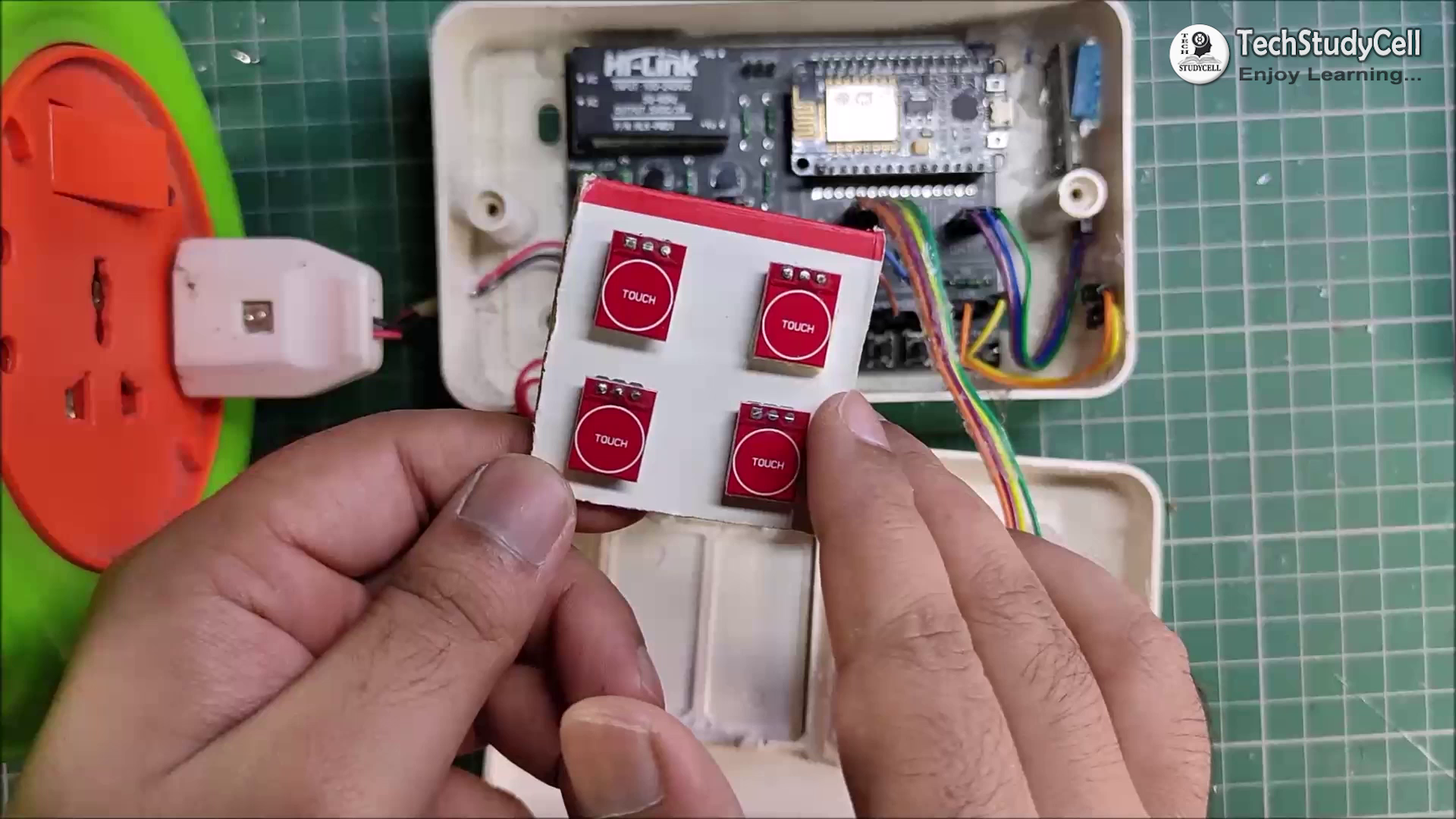
I have placed the complete circuit inside a plasic box. As I will use this NodeMCU project as Smart extention BOX.
It will be very useful and easy to use.
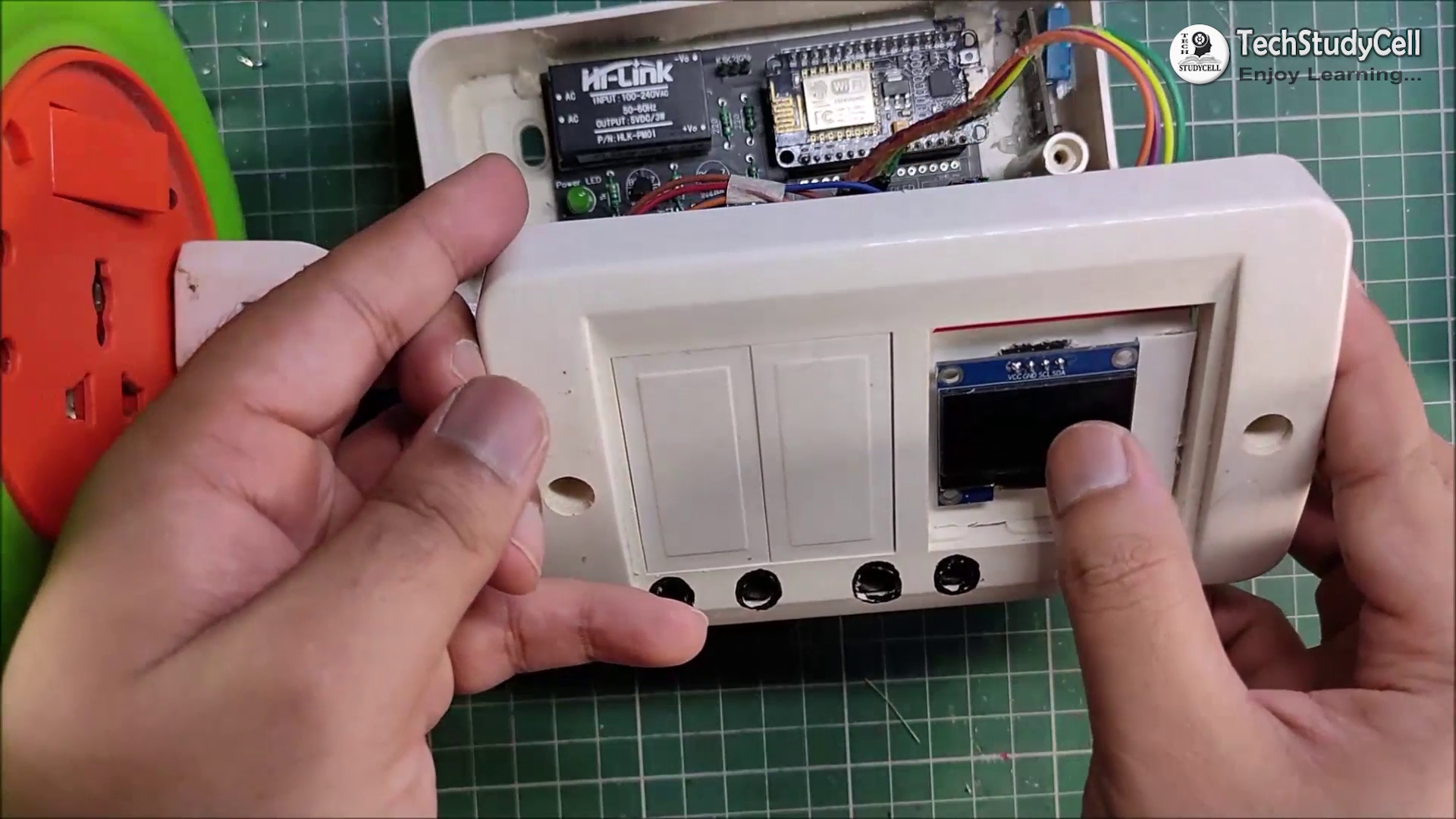
Finally the NodeMCU project is Ready:
Turn on the 110V/230V supply.
Now you can control your home appliances in a smart way. I hope you have liked this home automation project. I have shared all the required information for this project.
I will really appreciate it if you share your valuable feedback, Also if you have any query please write in the comment section.
For more such projects Please follow TechStudyCell. Thank you for your time & Happy Learning.