Annotated boards V1: buzzed out and hooked up. Note, I have no schematics, this is what I assume as I haven't tested yet. Just self notes.
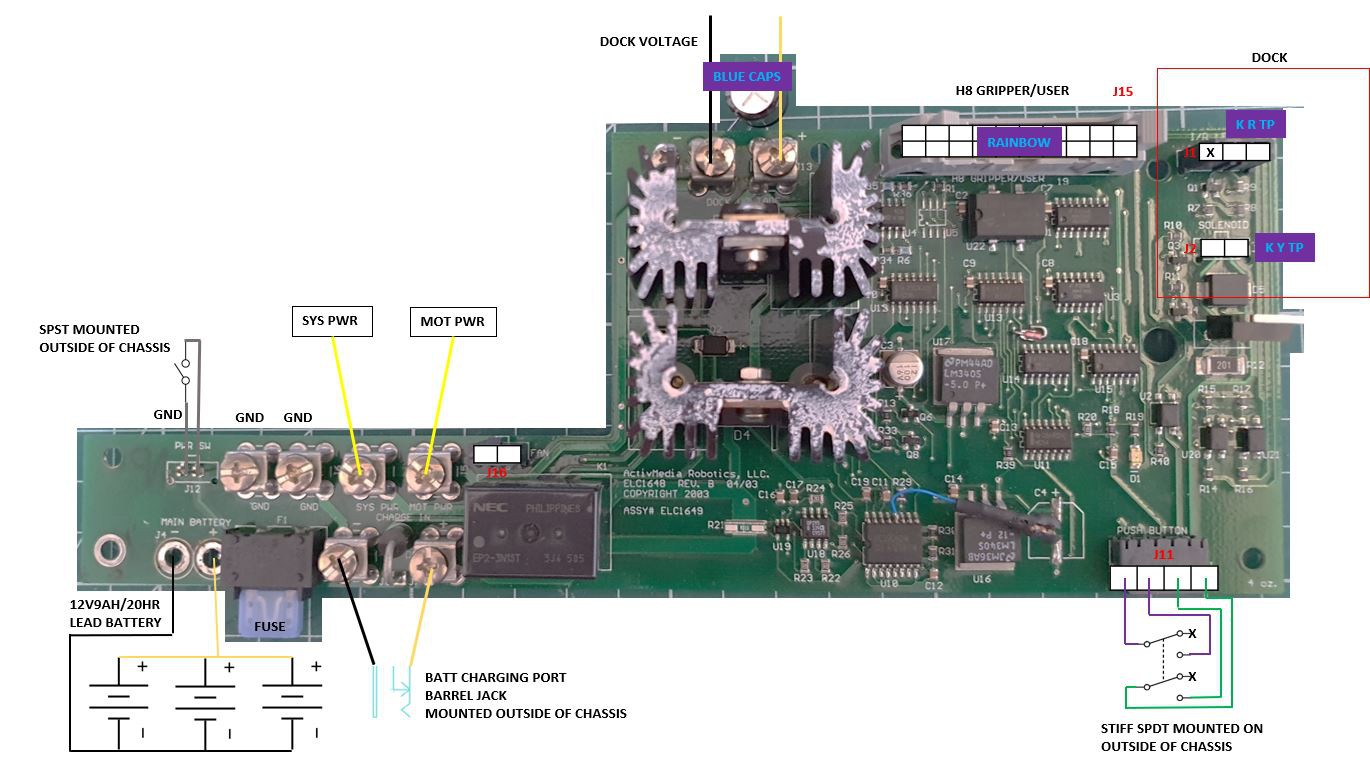 DOCK: Pioneer chassis has a self charging dock on the underside. Power board has a port J2 to control a solenoid which lowers an arm to make contact with pogo pins. I am assuming the robot aligns with the dock with IR, and that there are IR emitters supplied by the power board at J1 and receivers are connected elsewhere but it could be doing both from the power board. Dock charges through the dock voltage screw terminals J13-14.
BATT: Robot takes between 1 and 3 lead-acid batteries, 12V9AH/20HR, hooked up in parallel. There is a barrel jack mounted externally connected to J7-8, I assume this is for charging the batteries internally not powering external accessories. I have not fully buzzed the power board.
MOT: MOT PWR supplies the 12V to the motor board
SYS: SYS PWR seems to supply the motor driving circuit, have not buzzed out yet.
SPDT: There is a very stiff SPDT push switch mounted externally, I have no idea what this is for.
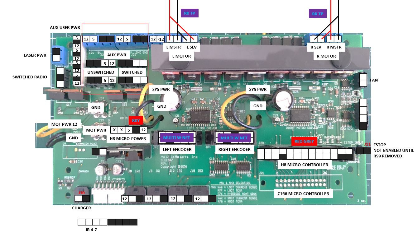
MOT: Motors powered through h-bridge, screw terminals at top of board. They have slave blocks adjacent that are directly linked to the left and right masters. Quadrature encoders are used on both wheels (diff drive), connected at left and right encoder ports.
IR: There seems to be 8 IR related ports, 4 have power and gnd with an unknown pin, there are 4 gnd on one port, and another 4 unknown pins on another port. I don't know if this is a research sensor or related to docking, does not look like anything has been connected to it.
AUX: There seems to be a bank of ports in the top left corner for powering additional sensors. Switched vs unswitched refers not to power supply but whether the power can be turned on or off using switches mounted externally. Main voltages are 12V and 5V, there is a -12V but I'm not sure where this is coming from. I suspect the board is designed to match the PC104+ standard which has 5V 3.3V -12V and 12V:
https://www.wikiwand.com/en/PC/104
PC: There is a 13pin cable between the internally mounted computer (IMC) and the motor board. There is also a 3pin cable between the computer and motor boards with 12V, 5V and GND. The board appears to allow for two separate computer setups, the "H8 Micro-Controller" and the "C166 Microcontroller" which is not set up. "H8 is the name of a large family of 8-bit, 16-bit and 32-bit microcontrollers made by Renesas Technology,"
ESTOP: Both pins of ESTOP are shorted to gnd, needs 0ohm R59 removed to enable.
I have no idea what the J38 3pin port is for?
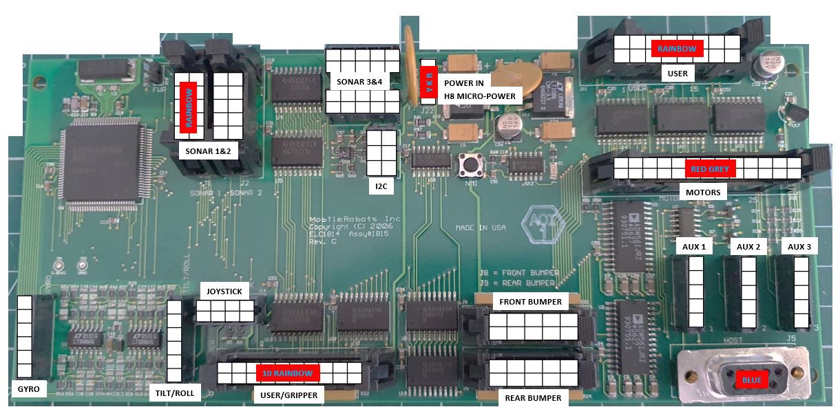 I intend to replace this with a more modern MCU. It takes gyro, tilt/roll, joystick, 3x sonar, motor, and the mysterious "user" connection. I'll figure out its communication with the motor board and replicate it on a newer MCU.
Again - this is guesswork notes for myself, probably very flawed
Discussions
Become a Hackaday.io Member
Create an account to leave a comment. Already have an account? Log In.