Previous work
A previous sensor that we designed was intended to be glued to the interior surface of a car tire or sports ball. The sensor requires zero maintenance in that it has absolutely no battery and never requires calibration. It is read AND powered by any smartphone with NFC capability (which is effectively all modern smartphones). Since the sensor requires no maintenance, the user never needs physical access to it, so it can be permanently embedded inside objects, and it will have an effectively indefinite lifetime. In order to fit the compound curves of tires and balls, the sensor was designed to be a flex sensor. The sensor was glued inside the tire or ball, and the scheme worked well, but repeated flexing of the sensor would often fracture the copper traces, causing sensor failure. A picture of one of the flexible sensor variants is below.
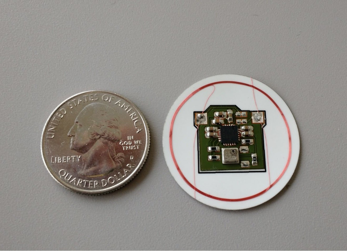
Additionally, it was difficult for end users to install, so we attempted to partner with OEM manufacturers of balls, tires, bikes, and other equipment. In the end, none of these partnerships made it very far, and we determined we needed a way to reach end users more directly.
Our original sensor use case was for bicycle tires. There are a couple primary reasons that a user would want to be able to accurately measure pressure: fixing flats during rides, or fine-tuning pressure on the trail. If a bicyclist has a flat tire during a ride, they may have a hand pump or CO2 inflator, but they are unlikely to have a pressure gauge in their kit. This makes inflating on the road or trail a bit of a guessing game. Inflate too much, and the tire ruptures and is unfixable. Inflate too little, and your ride is less efficient, or risks the chance of another flat if the wheel pinches the tube. So there are a couple use cases for bikes, but there seemed to be no good way for a sensor to access the pressure inside the tire, particularly for inner tubes. The original prototype cut a huge hole in the inner tube to allow sensor access! This is not remotely viable for end users to do.
New concept
Ultimately, the clear way to integrate the sensor into an inner tube is to access the pressure from the valve. Valve extensions exist for Presta valve types that effectively just make the valve longer. If the pressure sensor could be integrated into the valve extension, it would allow an end user to easily install the NFC pressure sensor. This concept is shown below.
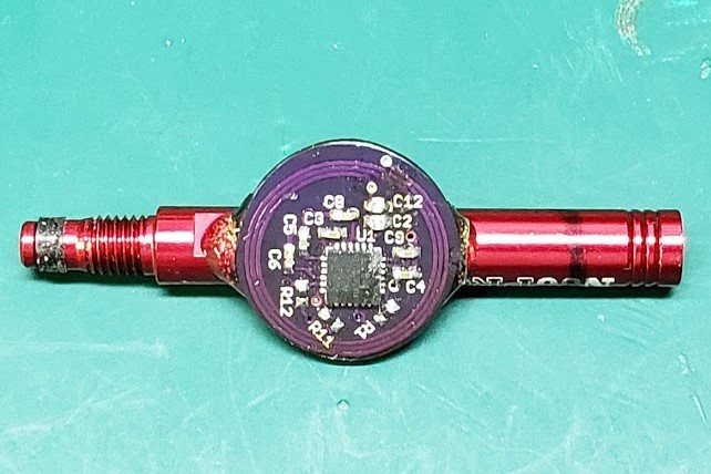
There are a few challenges in integrating the sensor into a valve extension. We need to 1) ensure that the sensor is small enough to not add too much weight or bulk, 2) ensure the sensor antenna needs to be isolated from the metal valve extension, which would otherwise kill the read range, 3) determine how to access the pressure inside the valve extension, and 4) completely seal the sensor to the valve extension to prevent air leakage.
1) Sensor size
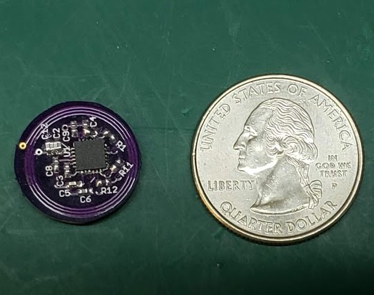
The primary challenge of this design is achieving acceptable sensor read range with a smartphone. This is particularly challenging, since the sensor requires more power than a standard NFC tag because it needs to power the sensor element and control circuitry. This means that with a given antenna size, this NFC sensor will already have worse range than an NFC tag with the same antenna. Aside from the overall antenna size, the read range is also dependent on the spacing between the copper traces of the spiral, the thickness of the spiral, and the number of spiral layers. We have performed research into these areas, and recorded empirical data in an attempt to optimize the range of a given antenna size. A view of the sensor assembly size relative to a quarter is below. Note how much smaller this sensor is relative to the original sensor. In spite of the size difference, the two sensors achieved very similar read range because the smaller antenna is much more optimized due to our research into antenna optimization.
Some of the work in antenna optimization is proprietary, but at a high level, the major publications we used to research spiral antenna optimization were "Simple Accurate Expressions for Planar Spiral Inductances" http://smirc.stanford.edu/papers/JSSC99OCT-mohan.pdf, "Design and Optimization of Printed Circuit Board Inductors for Wireless Power Transfer System", by Islam 2013 (https://www.researchgate.net/publication/271291453_Design_and_Optimization_of_Printed_Circuit_Board_Inductors_for_Wireless_Power_Transfer_System), and "Inkjet Printed Planar Coil Antenna Analysis for NFC Technology Applications,", by Ortego, 2012 (https://www.researchgate.net/publication/258384836_Inkjet_Printed_Planar_Coil_Antenna_Analysis_for_NFC_Technology_Applications). Ultimately, we were able to determine empirical expressions that were able to achieve a first-order range optimization. These allowed the development of antennas that were close to optional without requiring numerous antennas to be built.
2) Antenna metal isolation
The magnetic field lines from the NFC reader need to go through the center of the antenna and wrap back up around the outside. If the NFC antenna is placed near metal, the magnetic field is completely squashed by the metal under the antenna after it passes through the antenna. If we want to mount the sensor near metal we either need to ensure the antenna is appreciably far from the metal so it doesn't affect the range (which is hard to do in a small design since it just makes the design thicker), or we need to somehow steer the field away from the metal so it can't squash the field. Fortunately, this is fairly easy to do. RF absorber materials are readily available for specific radio frequencies, and it's easy to find one suitable for NFC. The absorber material (black material in the photo below) is a ferrite with adhesive backing, and it only needs to be mounted in the areas where the metal valve extension will ultimately be near the antenna. The RF absorber does affect the center frequency of the antenna, as does the ultimate placement on the metal object, so the antenna does need to be tuned to accommodate the RF and the metal.
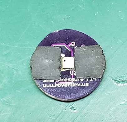
The mounting of the sensor on metal results in another interesting effect. One method for increasing the range of an antenna of a given diameter is to create a multilayer spiral. Spirals on multiple layers of the circuit board create mutual inductance and effectively increase the range. It's a second order effect, but it can improve the range by at least 10%. However, placing these spirals on multiple board layers puts them closer and closer to the RF absorber and the metal, significantly limiting the gains. In fact, we found in our testing that a multilayer design on metal with an RF absorber has WORSE range than a single layer spiral that is as far from the metal as possible (i.e. on the top side of the board away from the metal)
3) Pressure access
To access the pressure inside the valve extension, a hole can simply be cut in the extension. While we're at it, why not mill some flat surfaces into the extension to which the sensor may be mounted? Using a very cheap CNC mill, we were able to repeatably mill a pressure access hole and flat mounting points into off the shelf valve extensions as shown below.
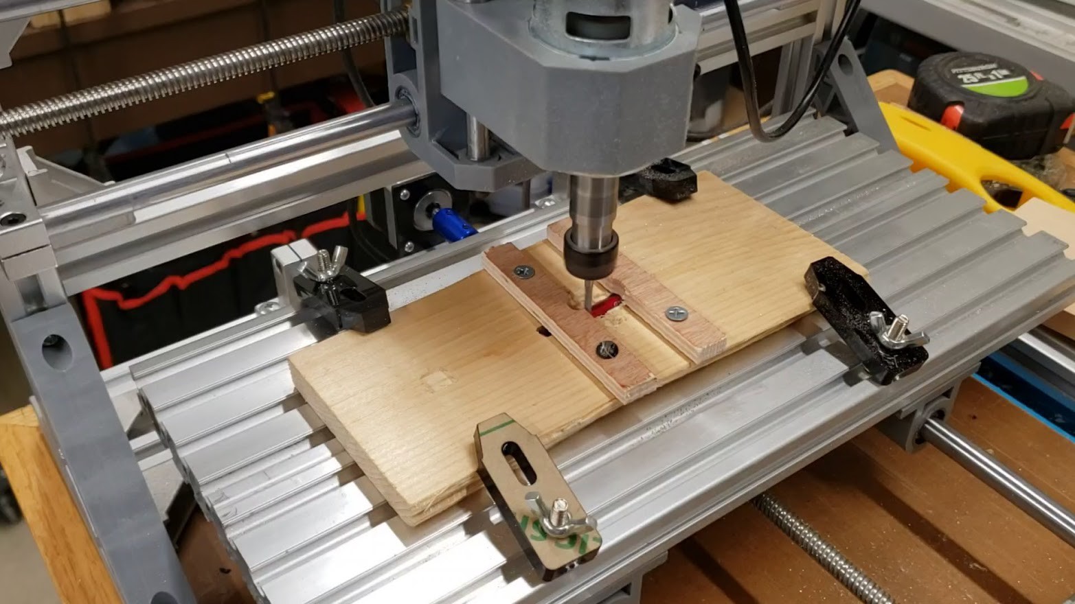
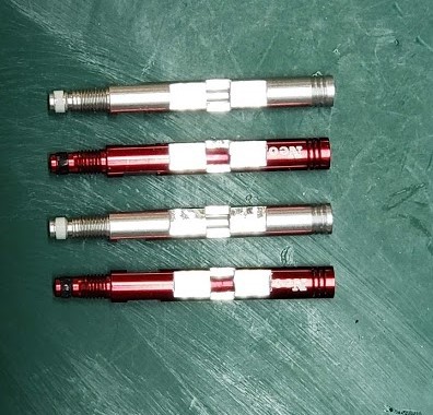
First, a simple fixture was made by milling a slot into a piece of wood that was the exact width of the extension, but not quite as deep so the extension would stick up above the wood. With some of the extension sticking above the board, securing the extension was as simple as screwing two pieces of wood over the extension to hold it down tightly. Then a different CNC program was loaded to mill the flats and slot into the extension. Milled extensions are shown below.
The read range of an NFC tag or sensor tends to grow proportionally with antenna size - a larger antenna will generally have a longer read range. However, certain applications like a bike valve aren't as able to accommodate larger antennas. Moreover, bike tire valve and extensions are generally made from metal, and mounting NFC antennas near metal can significantly reduce their range. The optimization of the antenna for the application is therefore critically important to achieve good readability and usability.
4) Sealing the sensor to the extension
None of the design work above is useful if the extension leaks too much air. The whole point of using the extension to check pressure is moot if it causes the pressure to leak out too quickly. Ultimately, it is probably possible to use injection molding of an elastomeric plastic to both seal the sensor to the extension and to permanently mount the two pieces together. This was attempted with a first prototype, but the plastic used (polypropylene) wasn't soft enough to form an airtight seal to the aluminum insert. Ultimately, we chose to first use a somewhat flexible epoxy as a preliminary bonding/sealing step as shown below. The epoxy is clear and a fillet of epoxy can be seen between the sensor and the extension.
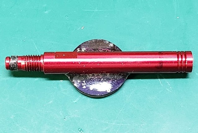
This epoxy was able to achieve excellent mechanical bonding and sealing between the extension and sensor. We could have also encapsulated the whole thing in another layer of epoxy in an attempt to improve the durability of the sensor/extension bond if it were hit by something on the trail. However, we had a better idea.
This is the really neat part of this project. We have a PIM shooter Model 150A, from techkits.com. This is a small scale, hand operated injection molder, as shown below.
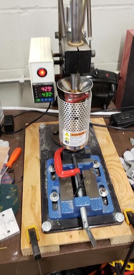
The Model 150A is generally used with small molds, which can be designed and machined from aluminum. However, we wanted to test several different molds during prototyping, and we didn't have the capability to mill aluminum molds in house. Testing different molds would have been very costly if each mold design needed to be outsourced. However, we have a Stratasys FDM printer available, and even though it seems like a crazy idea since the melting point of ABS is close to or even potentially LOWER than the melting point of the plastic we wanted to inject, we thought we'd give it a shot.
A mold was designed in CAD and printed in ABS. Location pins were mounted in the mold by drilling small holes and gluing steel pins in place. These location pins are used to ensure the sensor remains in the correct orientation during molding. The pins actually touch the circuit board of the sensor in four places, as seen in the left half of the mold in the picture below.
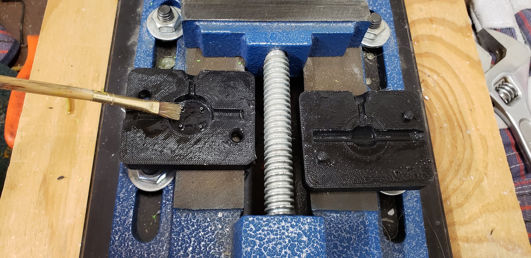
The injected plastic will want to stick to the ABS mold, partially due to the ridged texture of the FDM print, and partially due to the fact that the ABS melting point is so close to the injected plastic's temperature. A mold release agent will help prevent sticking of the injected plastic to the mold. We mixed the mold release by dissolving petroleum jelly into Naphtha mineral spirits and applying with a paintbrush as shown in the picture. This mold release is fairly messy, but it does ensure the injected plastic never sticks to the mold.
The sensor is placed in the two mold halves, with the locating pins touching the sensor so the extension can't move or twist when the high pressure liquid plastic enters the mold. Then the mold is clamped shut with a C-clamp, placed in the Model 150A's clamp, and the handle is pulled down.
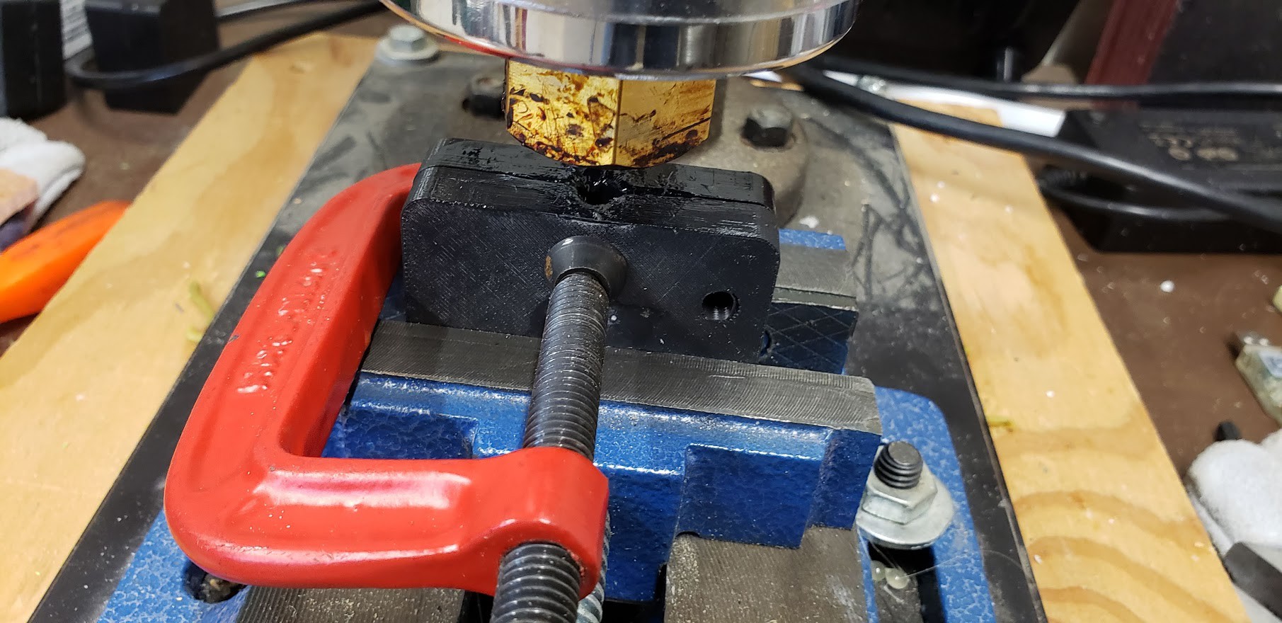
There were no issues with the molten plastic damaging the mold, but the hot nozzle does deteriorate the mold a bit over time, as can be seen in the image above. If it deteriorates too much, another mold can be printed, or when the ultimate design is determined, a long-lasting aluminum mold can be machined with the final design.
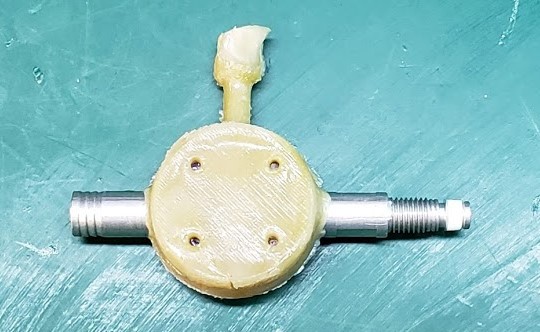
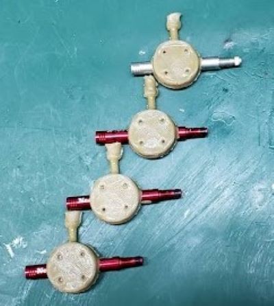
Ultimately, the designs molded very well and are water and airtight. The plastic completely protects the sensor and bonds it to the extension, and the pressure is easily read from inside the valve extension by holding the back of a phone up to the flat circular portion of the sensor assembly. The location pin witness marks are easy to see on the top side of the sensor, but they do not impact the water tightness of the sensor. The gate vestiges are left on the sensors in the images below for illustration.
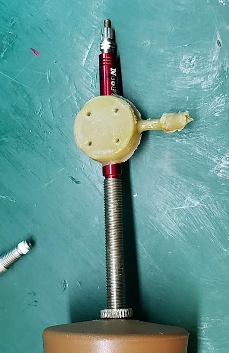
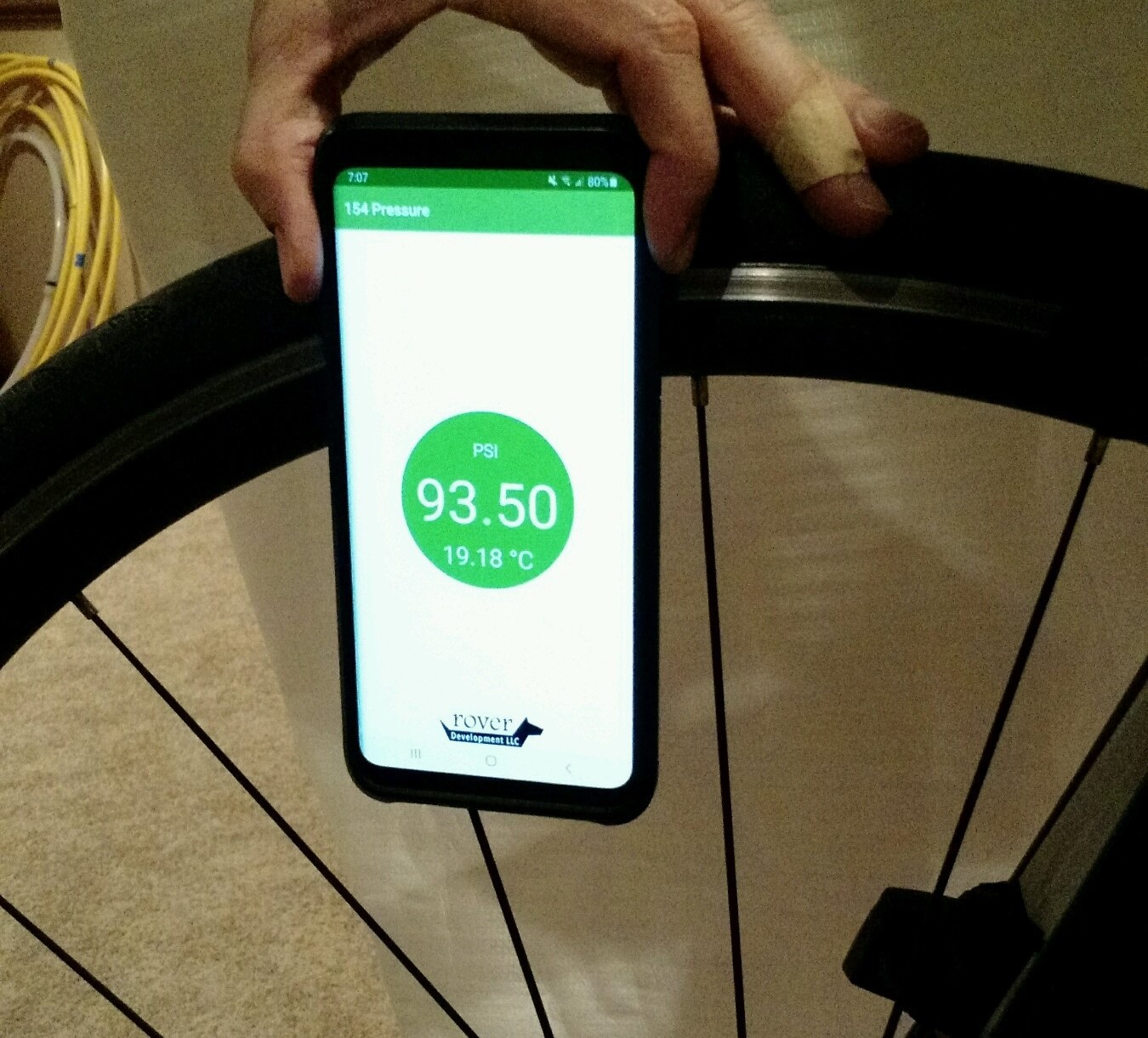
In order to use the assembly on a Presta bike valve, the valve core (at top in the image below) must be removed. Nearly all Presta valves for tubeless tires have removable valve cores. Only some inner tubes have removable valve cores. Removable valve cores are required to use this design, but it is possible to create a similar design that does not require removable valve cores. After the valve core is removed, the extension assembly is screwed in its place. Then the valve core is screwed in the top of the extension. The tire is inflated and deflated through the valve core as usual, and the pressure is read by holding the back of a smartphone running our app up to the sensor. This automatically powers the sensor and reads its pressure.
Next steps
This valve extension is perfectly suited as an aftermarket product for bike enthusiasts. The design and assembly are fairly well understood, and ready to be scaled up with high volume injection molds. We are considering a crowdfunding campaign to design and purchase insert mold tooling for a product. We are also developing designs suitable for use with Schraeder valves like those used on other bicycles and on cars, trucks, ATVs, and other vehicles. We're interested to hear from you with questions or suggestions. Please check us out at www.roverdev.us.
 CaptMcAllister