Riccardo Pellegrini
Browsing the social media of electronics enthusiasts I found a pokèmon-style PCB and I thought I'd make one too. (https://www.instagram.com/p/CG6-QrbrVJ8/?utm_source=ig_web_copy_link)
I continued my research to find out if anyone had created a PCB based on my favorite pokèmon that is Umbreon and I found the following keychain where a black soldermark and a gold finish were used to get the pokèmon color pattern. (https://imgur.com/gallery/Zhk9J)
I wanted to do something similar but original.
I looked for an alternative to USB power, and WPT seemed like the optimal choice.
I asked a friend of mine to draw the pokémon for me, she is a very good drawer and illustrator, you can find her instagram profile at the following link:
https://www.instagram.com/dfane.dsp/
I also thought of using one side of the PCB to draw an ultraball that has the same color pattern as Umbreon.
I decided to make 2 prototypes
- using the standard for inductive charging
- trying to rectify the small transmitted power in the absence of a chip that uses the standard
The right way to design
I looked for the standard used by the WPT and found that it is Qi.
https://en.wikipedia.org/wiki/Qi_(standard)
Googling "Qi IC" I found BQ51013 from Texas Instruments, this is an advanced, integrated, receiver IC for wireless power transfer in portable applications.
The schematic is easily found in the datasheet, the only unknown was the coil. I tried to design one with inductance similar to the one mentioned in the datasheet with a value of 10.4 μH.
Using ADS I found the right size to get this value with a high quality factor.
To insert the coil in kicad I used the following python script.
https://gist.github.com/JoanTheSpark/e3fab5a8af44f7f8779c
After that, I simply copied the schematic into Kicad. Thanks to JLCPCB that offers an assembly service, I was able to use 0201 components obtaining a very compact design despite the presence of many components.

The other way to design
Using wires I created a coil that I placed above the WPT transmitter, with the oscilloscope I saw that in certain time intervals I could read a decent voltage with which I was able to turn on a LED.
I modified the previous coil trying to get the highest quality factor possible at 140 kHZ, surprisingly my previous design was already very close to the optimal one.
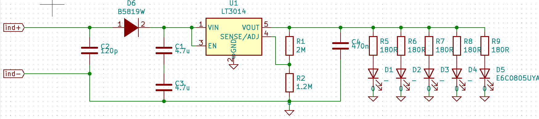
I created the schematic with Kicad to rectify the voltage, I added a voltage regulator to protect the LEDs, I chose to insert a capacitor in parallel to the coil to amplify the voltage received by resonance and I chose all the components so that they could withstand high voltages.

Results
I made small mistakes in both designs but nothing that can't be fixed with a few patches.
PCBs that use the Qi standard communicate with the transmitter and require continuous delivery of power. On the contrary, the other PCBs normally blink. By placing both types above the transmitter, it is possible to have a constant transmission on both of them.
 Sagar 001
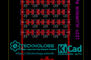
 Chromico
 Tony
Tony