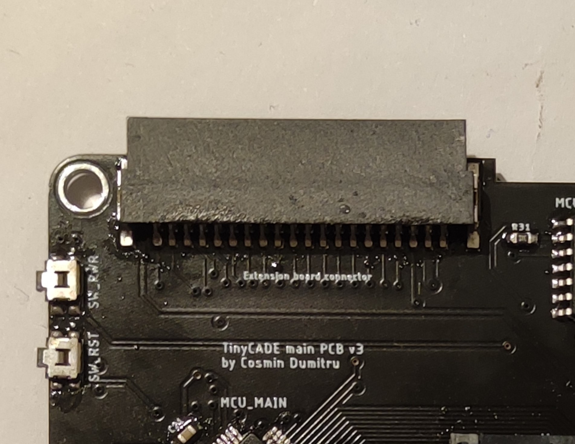
To be honest, the previous TinyCADE PCB was not too good: the extension board was attached via a standard 40 contacts, 1.27mm pitch pin header which wore out after a few dozen cycles and was quite unreliable, a humming sound was constantly present in the speaker (as a bonus, the brighter the OLED, the louder the sound), the ATtiny212 microcontroller (responsible for power management and timekeeping) would hang unexpectedly when communicating with the AVR128DB64 via I2C (details at the end of the log) and the component layout was quite messy. I really hated it.
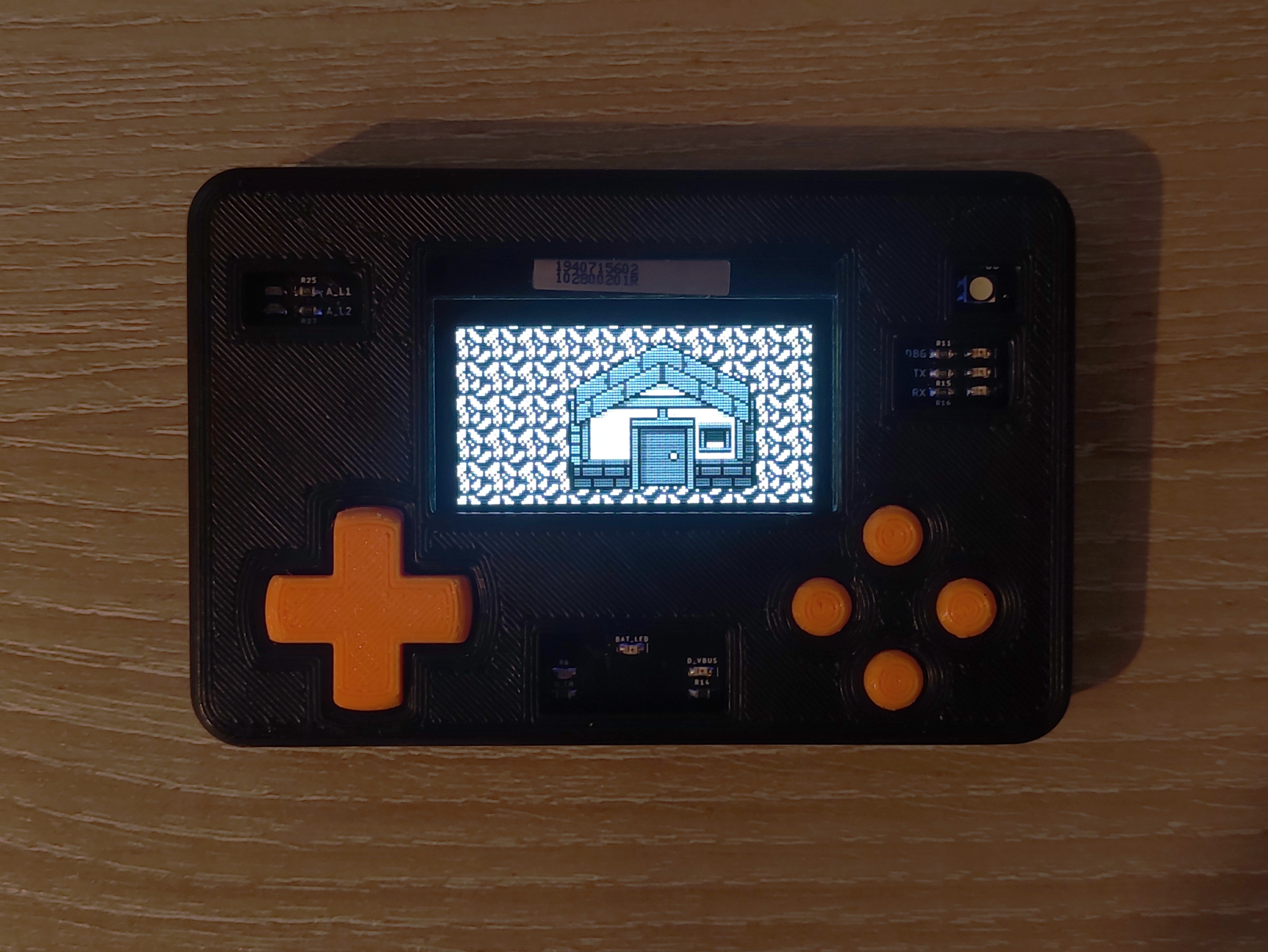
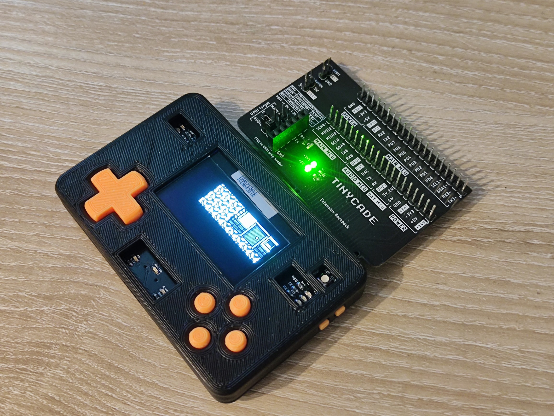
I received the PCBs for the latest TinyCADE iteration for free about 2 months ago, from JLCPCB through their Student Sponsorship Program (https://jlcpcb.com/RAT) and after a lot of soldering it looked like I managed to fix all of the problems mentioned above. I decided to celebrate by offering TinyCADE a 3D-printed, spray-painted enclosure and buttons (the same model as in the renders) using PLA (that's what I've had at the moment).
Also, I have been working on an Arduino library for TinyCADE. Check out the GitHub link on the project page. I will also publish the power management microcontroller and synth source code when the project is finished.
The PCB "remaster"
After redesigning the whole PCB using better practices, all the speaker humming was gone. Only a faint white noise can be heard by sticking my ear onto the speaker. Also, I modified the BOM to have IC's with better availability because of the global chip shortage.

Messy stuff. A busy city can be seen on the left, and a desert on the right. Let's not talk about the mounting holes and the ground plane :)

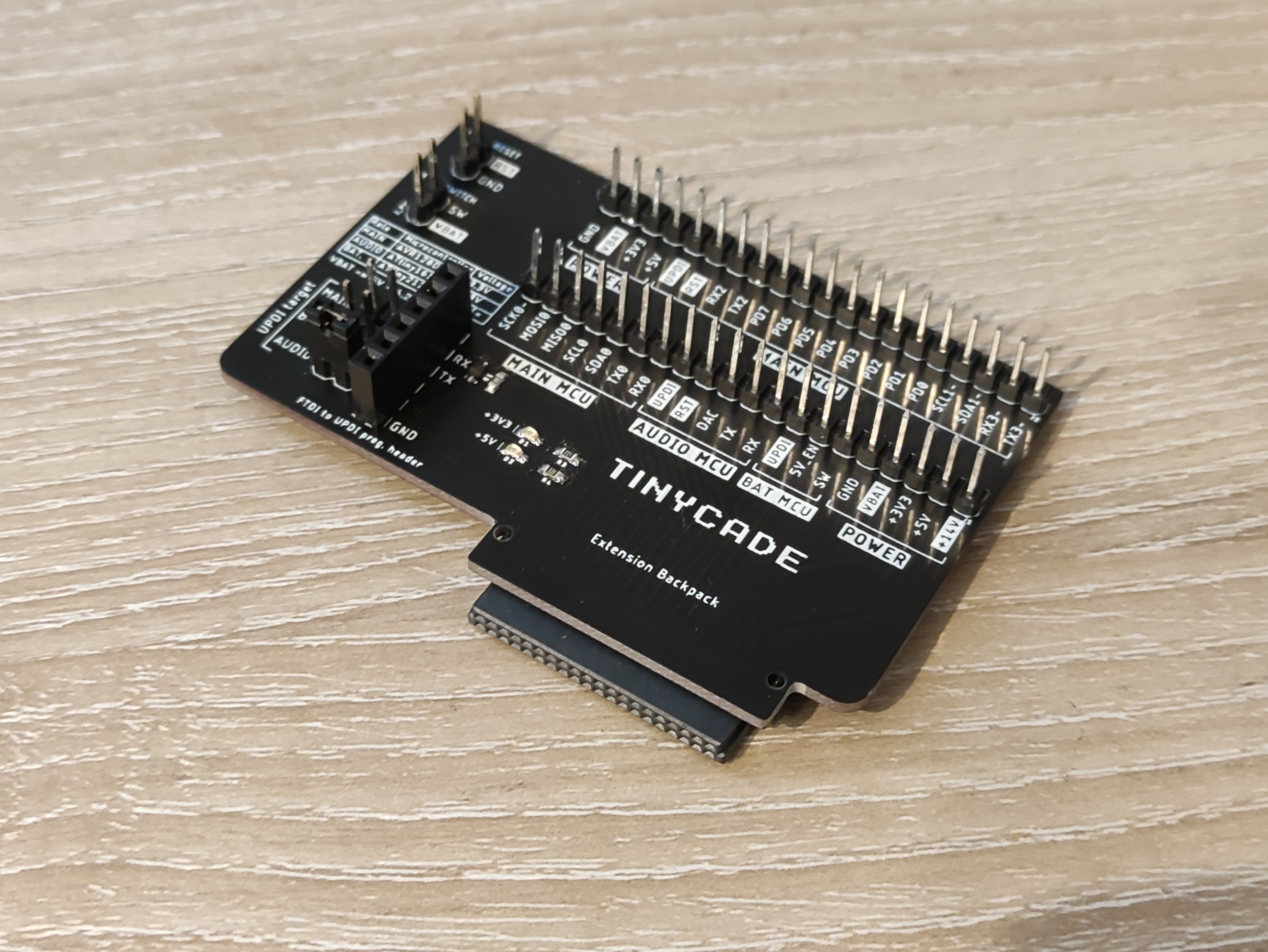
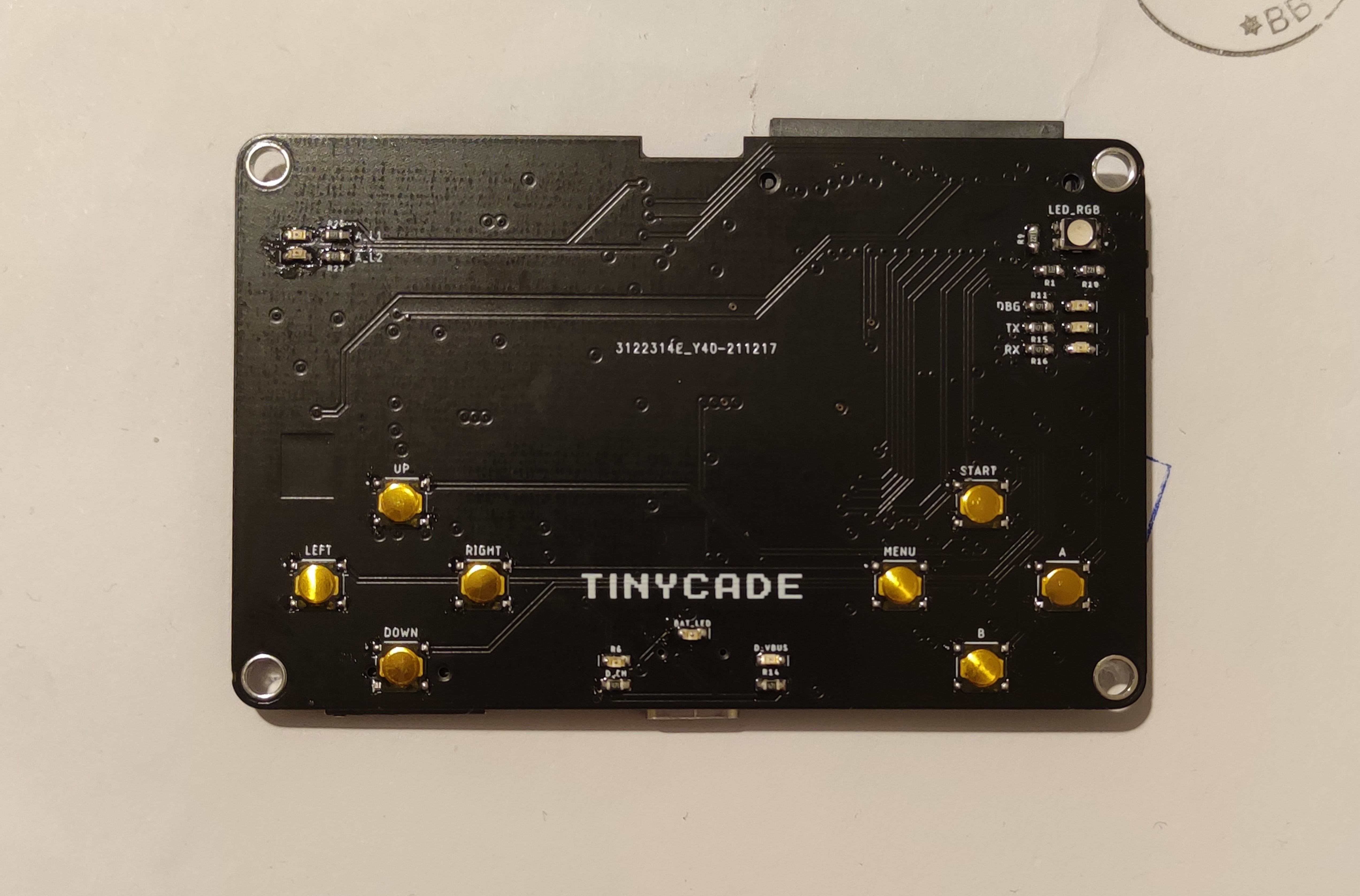
Also, I replaced the Extension Backpack connectors with these bad boys from Harwin: the M55-6104042R and M55-7104042R. Here is how the real TinyCADE looks, apart from the renders:
What's going on with the ATtiny212?
This tiny, but mighty microcontroller with just 128 bytes of SRAM, 2Kb of flash and 64 bytes of EEPROM acts as a power manager. When TinyCADE is turned off it enters power down mode, bringing the total current consumption down to a few μA. Only the PIT interrupt of the internal RTC fires up every 1 second for incrementing a 32-bit integer which acts like a timestamp.
When the power button is pressed, a pin change interrupt is fired and the 5V boost converter is enabled, having the role of the main power supply of the device (PAM2401 IC), powering the 3.3V regulator and the +14V boost converter for driving the OLED. During the time when TinyCADE is on, it "listens" for commands formerly received via I2C, monitors the battery voltage and if it falls below a hardcoded threshold, the the 5V boost converter is disabled and the ATtiny enters power down mode to help protect the battery, which also has a PCM including over-discharge protection.
The I2C problem
In the previous iteration, the ATtiny212 was acting as a slave, while having the AVR128DB64 as a master on the I2C bus. The problem is that the master power supply was dependent to the 5V boost converter, while the slave was always powered up from the LiPo battery. Also, 10k resistors were used on the SDA and SCL pins for pulling the lines up to 3.3V, which had the same problem. This led to more checks to be done, while also increasing the already large I2C implementation footprint on the small 2Kb flash memory of the ATtiny.
Also, the AVR128DB64 had to keep polling the ATtiny to check if the device is about to shutdown, causing overhead to the main application.
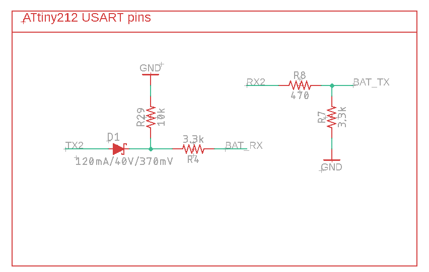
In the current version, the ATtiny212 communicates with the AVR128DB64 via USART, using a simple logic level conversion circuit for not destroying the main microcontroller pin with ~4.2V on high state, when the battery is fully charged.
This way, the protocol implementation is much more straightforward, reducing its flash footprint to about 300 bytes of compiled AVR Assembly (including peripheral initialization, interrupts and read/write routines with rx/tx buffers).
Moreover, since the transmitting and receiving pins are now separate, the AVR128DB64 no longer needs to poll the ATtiny212 for incoming device shutdown, so I feel like I've made a good decision to replace I2C with USART for this application.
I am aiming to have main microcontroller notified approx. 500ms prior to shutdown in order to have enough time to properly turn off the OLED and cancel any ongoing operation, for example writing a file to the inserted SD card.
Discussions
Become a Hackaday.io Member
Create an account to leave a comment. Already have an account? Log In.