The key components in this board are the MCP2561/2FD and the 40 Pin GPIO Header which will be used to interface with a Raspberry PI 4 to test whether CAN Data can be sent to a Pi properly.
The MCP2561/2FD is a cost-effective and small-footprint CAN FD controller that can be added to a microcontroller with an available SPI interface.
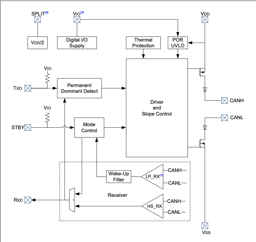
It has the following features:
- VIO Supply Pin to Interface Directly to CAN Controllers and Microcontrollers with 1.8V to 5.5V I/O
- Power-on Reset and Voltage Brown-Out Protection on VDD Pin
- Protection Against High-Voltage Transients in Automotive Environments
- Very Low Standby Current (5 µA, typical)
- High ESD Protection on CANH and CANL
The Raspberry Pi 4 is a credit card-sized computer system and comes with a high-performance ARM Cortex A72 4x 1.5 GHz quad core processor.
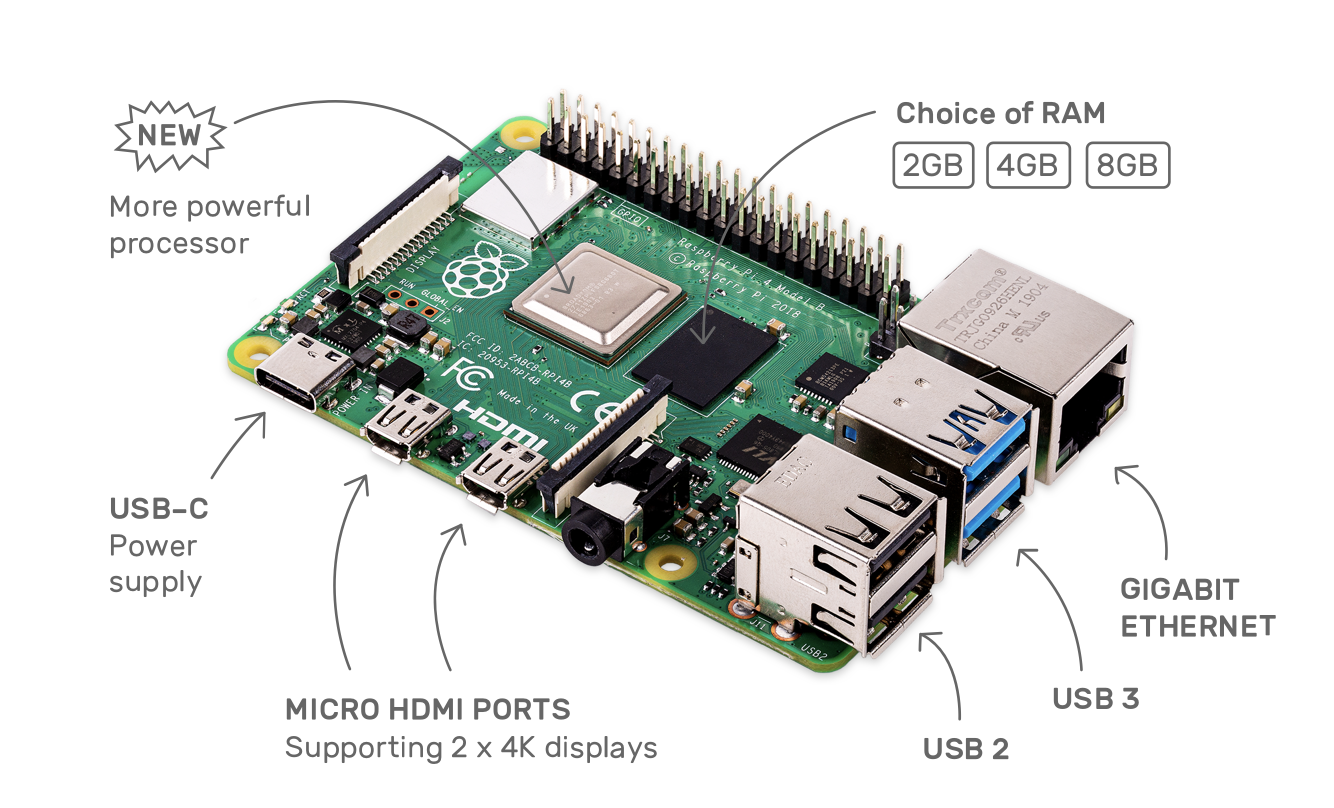
It has the following features:
- Quad core 64-bit ARM-Cortex A72 running at 1.5GHz
- 1x SD Card
- 2x micro-HDMI ports supporting dual displays up to 4Kp60 resolution
- 2x USB2 ports
- 2x USB3 ports
- 28x user GPIO supporting various interface options:
- High operating range of 0 to 50 degrees Celcius
 Avi Gupta
 simon
simon
 Robert Hart