 Scott Gillins
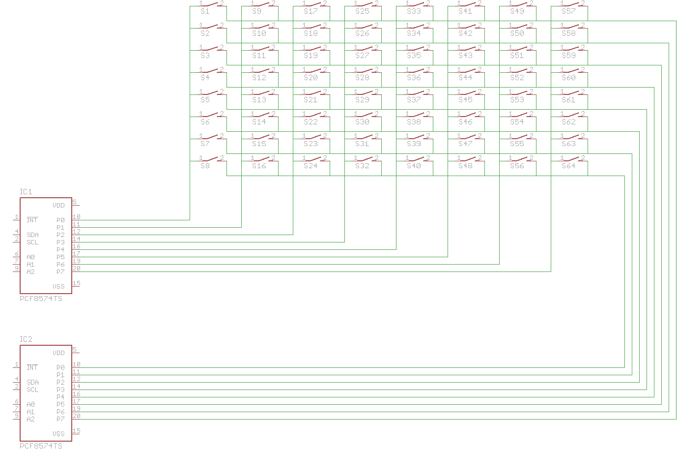
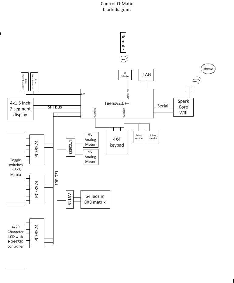
This project is continuing to evolve over time. Current and planned features include over 50 leds, 40 switches, 2 missile launch switches, 2 key switches, 2 sliders, large 4 digit number display, 4x20 character display, 2 analog meter indicators, 2 rotary encoders, infrared remote control and a 16 digit keypad.An internet connection using a spark core is currently being integrated. This will allow live updates from the internet or an app.
The case is made of 5mm clear acrylic.The pieces were laser cut and then put together with acrylic weld and screws.The current design was made too small with no room to put switch or indicator labels.It may be better to have made the case out of wood with a clear top or completely out of wood.I wanted it so the insides could be seen.I guess time will tell with the materials choice.
 Tony Keith
 adi-miller
 allexoK
 Paul Whitaker