 Guillermo Perez Guillen
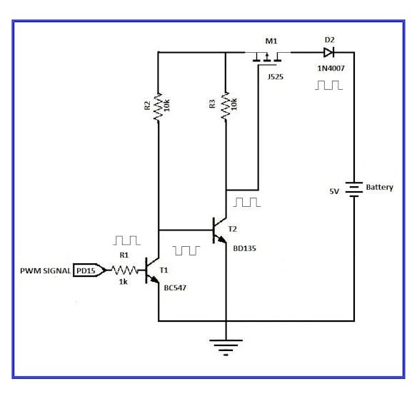
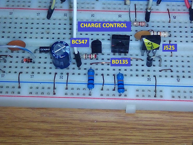
Circuit diagram of the charge control
How does it work?
a) The voltage measured in Vcc in this circuit with the voltmeter indicated 5, 45 volts. In this example I´m using a module of four rechargeable batteries of 1, 5 volts. The maximum load voltage will be 5.6 volts. I used Nickel Metal Hydride Batteries, and we can find the international standards here: https://www.mpoweruk.com/standards.htm
b) The PWM signal generated by the STM32F407VG board will be used to regulate the load that goes to the rechargeable battery. To generate this PWM signal, we take the example "demo_timer_pwm" from "Ada Drivers Library" and modify it to obtain our desired PWM signal. For example, if the battery is completely discharged, then the PWM signal has a large duty cycle.
c) Transistor T1 was used to physically separate the STM32F407VG board and the M1 Mosfet. If they were directly connected, then this device would be damaged, since the Mosfet works with very high loads. The resistance R1 (1k) must be of a low value to increase the switching speed of the PWM signal.
d) However, at the output of transistor T1 we have an out-of-phase signal 180 degrees, and to adjust this situation, we make use of transistor T2, and now the PWM signal is in phase.
e) To drive the cutt-off and saturation regions to our T1 and T2 transistors, we make the following considerations:
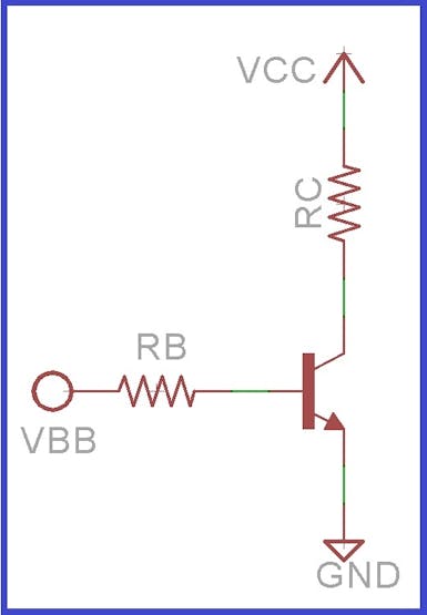
Common emitter
To determine the saturation current, we consider the emitter collector voltage of the output grid equal to zero. Thus:
VCC=IC*RC+VCE | VCC=IC*RC+0
IC=VCC/RC
To determine the cutt-off, we consider that the base current is equal to zero, therefore the collector current is equal to zero:
VCC=IC*RC+VCE | VCC=0*RC+VCE
VCE=VCC
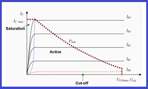
Graph of the cut-off and saturation region of a common emitter amplifier
f) The protection devices used are the following: Capacitor C1 and Diode D2. The diode serves to eliminate the reverse direct currents of the battery when it is fully charged. If this diode didn´t exist, then the battery would induce voltages in the transistors T1 and T2.
We control the charge of a rechargeable battery by means of a P-channel MOSFET, and two transistors
Discussions
Become a Hackaday.io Member
Create an account to leave a comment. Already have an account? Log In.