Benchoff
-
Test badges done, work begins on Art & Firmware
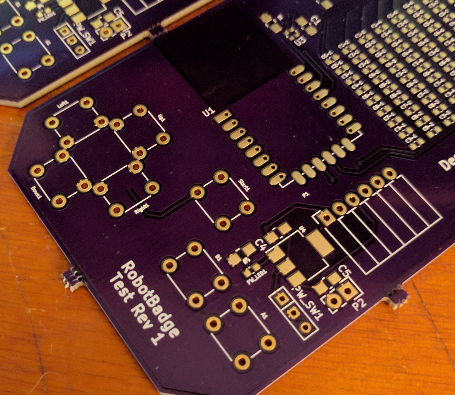
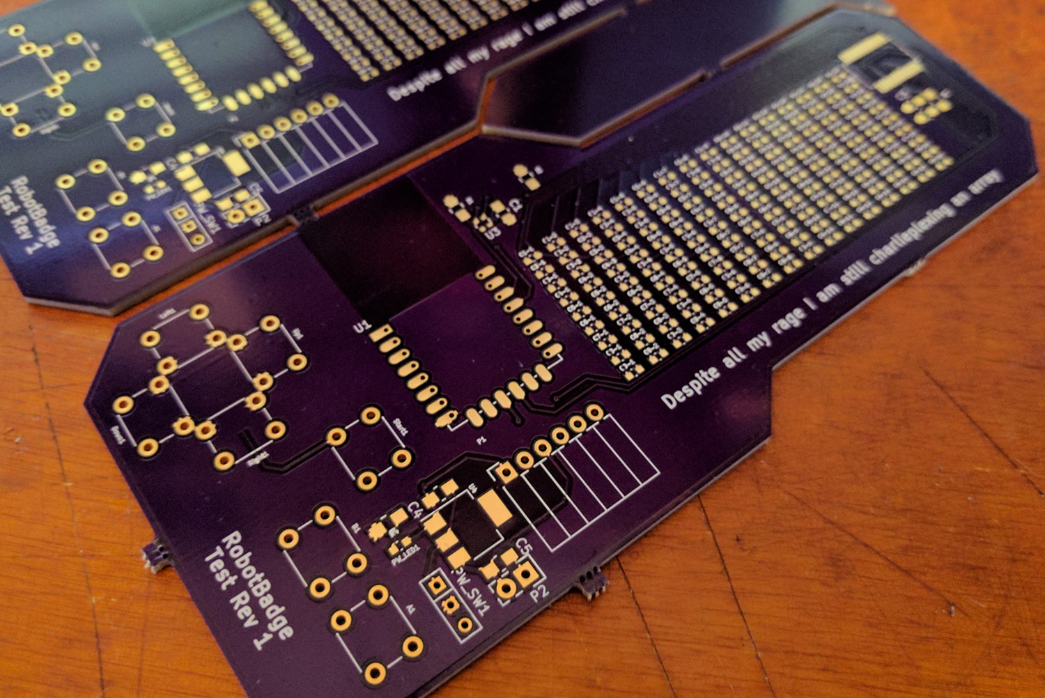
02/22/2017 at 05:47 • 0 commentsThe test badges are complete. After a stupid mistake with copper fills and KiCad, I have an electrically complete badge. Some of these were sent off to the firmware devs. Once the entire circuit is confirmed working and power analysis is done, I can begin designing the complete badge.
![]()
ART
Before I begin designing the badge, I have to work on the one killer feature of this badge: a three-color image of the famous Mr. Robot 'mr. monopoly' mask. After about 10 hours in Illustrator, this is what I have:
![]()
Yeah, that looks cool. This is effectively a render of what the back of the badge will look like. Technically, this isn't a three-color PCB. Instead, the only 'color', per se, is the beige / skin tone. The white and black will be two processes of silk screen. This makes fabrication easier (and cheaper), since it's effectively only a second silk screen process on one side.
Of course this does make translating this into KiCad a bit difficult. It's a lot of work with illustrator layers, dividing objects below, and messing around with paths. Here's what the layers look like when separated:
![]()
It makes sense when you think about it.
Once the circuit is confirmed working, I'll be altering a few things (QFN for the LED driver instead of the SOIC - I can't buy enough SOICs for this project, moving to SMD tact switches, figuring out the battery holders) and doing a Revision 3 spin of the board using only the outline layer. Once that's confirmed, it's off to China to find a board house to make all these badges.
-
Protoboards Are In
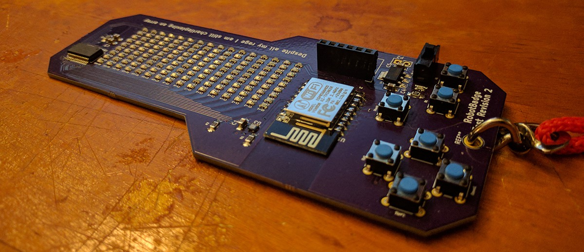
02/03/2017 at 19:45 • 0 commentsNow to populate 144 LEDs six times:
![]()
![]()
-
First Prototype Board
01/22/2017 at 20:59 • 0 commentsAfter a few discussions with the confederates in this experiment, we've settled on the hardware and physical features of the badge. They are:
- Built around ESP8266-12 module. This gives us WiFi and enough GPIOs to do something interesting
- 16x9 LED array. This is driven by the I231FL3731 charlieplex array driver. It's a cheap chip, and should work.
- Seven buttons. Up, down, left, right, A, B, start.
- Ambient light sensor. We're using the Lite On LTR-329ALS-01. Cheap, and connects directly to I2C bus
- That's about it.
This is more than sufficient for a test board. Right now, six of these boards are sitting in the OSHPark queue, and in two weeks I'll have some test hardware.
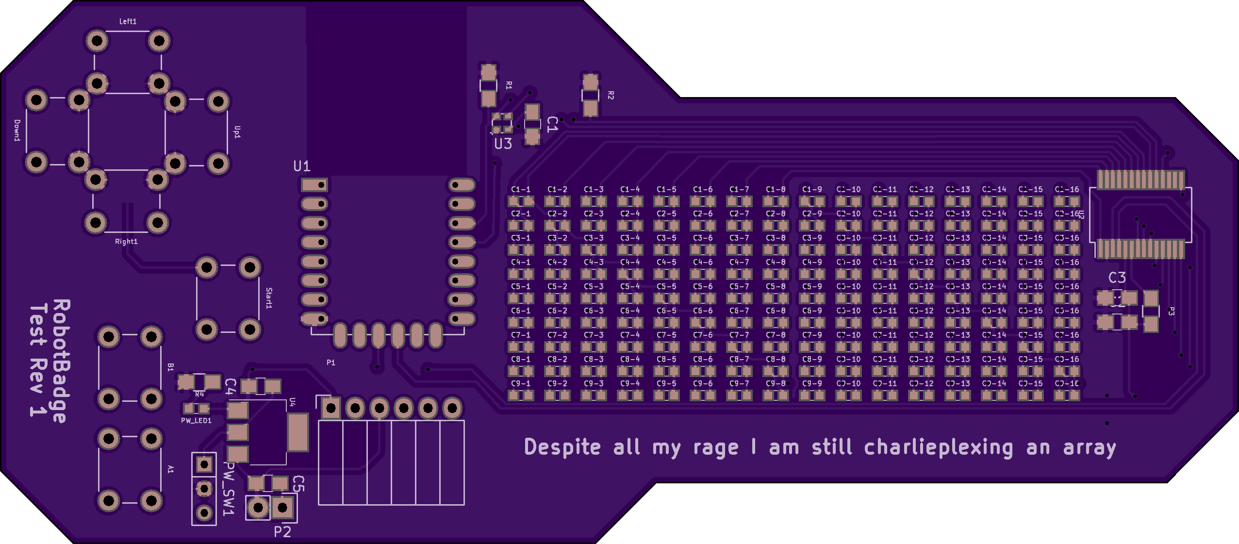
The Schematic And (test) Board Art:
![]()
![]() Oshpark render, with Mellon Collie reference:
Oshpark render, with Mellon Collie reference:![]()


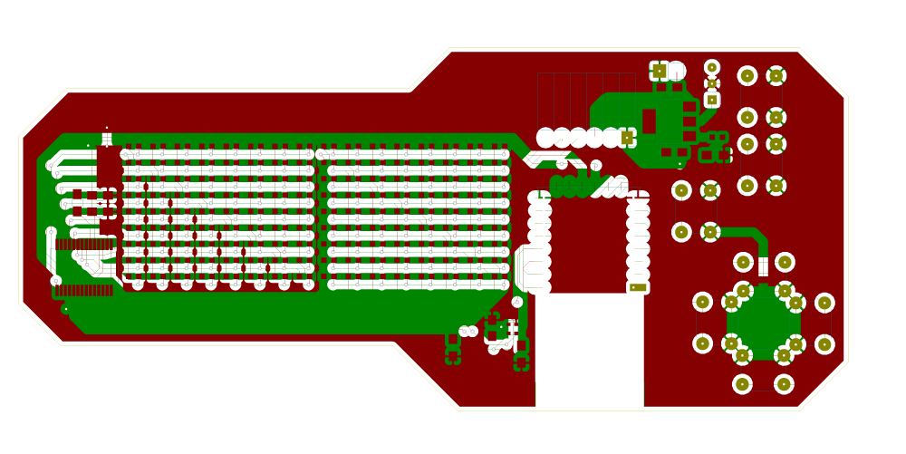
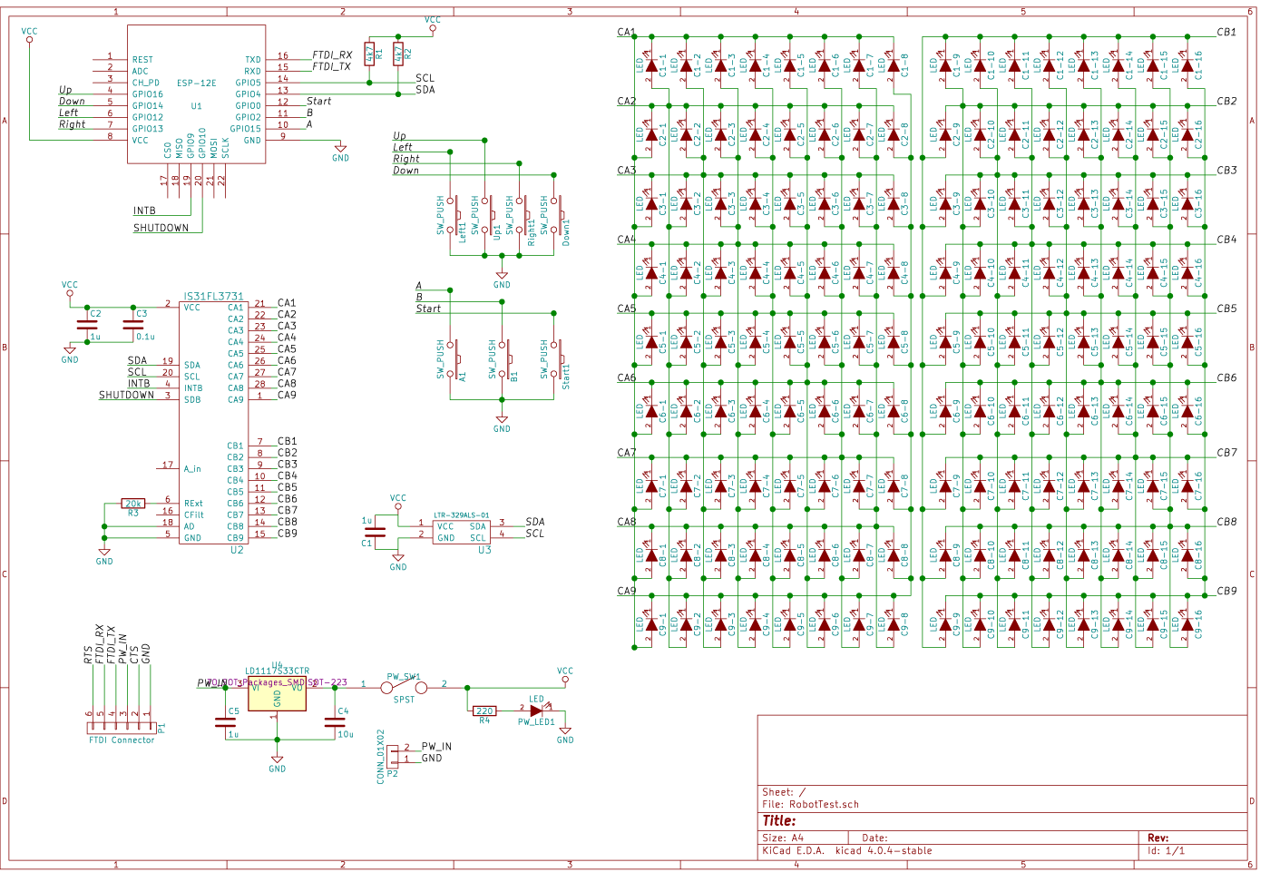 Oshpark render, with Mellon Collie reference: