ElectronicABC
GERBER PCB:
https://mega.nz/file/jEAnyKTJ#vFj6t6YB-yaMHNf_yhgNuXVvKvPBmx3rEFv0QIMAIKE
DATASHEET SCR C106DG:
https://mega.nz/file/TN5RRK5J#LuROspQhA5OpTO6GbCLjuvHn70rFaZUFlkAKdgf7k1Y


Direct starting is the simplest method of starting a three-phase induction motor. It simply consists of connecting the stator windings directly with the closure of power contacts (contactors).
In this project we will develop the control system.
The main brain of this project is the SCR, which is an electronic device where, when a positive pulse arrives at its gate or GATE, it will drive in one direction from ANODE to CATHODE, so we will use it for the interlocking of the system.
SCR:
The silicon controlled rectifier (SCR) is a type of thyristor made up of four layers of semiconductor material with a PNPN or NPNP structure. The name comes from the union of Tiratrón (tyratron) and Transistor.
Thyristor:
An SCR has three connections: anode, cathode, and gate. The gate is responsible for controlling the flow of current between the anode and the cathode. It basically works like a controlled rectifier diode, allowing current to flow in only one direction. As long as no voltage is applied to the gate of the SCR, conduction does not start and the instant that voltage is applied, the thyristor starts to conduct. Working in alternating current, the SCR is de-excited in each alternation or half cycle. Working in direct current, a forced blocking circuit is needed, or else interrupt the circuit.
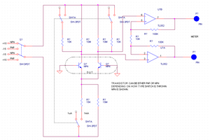
HOW DOES IT WORK?
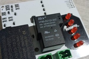
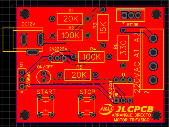
The operation is very easy when we start it, it will send a positive pulse to GATE and leave it locked so it will stay on and at the same time activate the MOC 3021 which is an optotriac and will turn on its input and at the same time turn on its output to a TRIAC. BT 136. Once the 220VAC voltage is allowed to pass, the contactor coil will be activated to start the three-phase motor and when we press STOP, it will send a negative pulse to the base of the 2n2222a transistor that will deactivate the SCR for a moment and return to normal initial state.
ELECTRONIC COMPONENTS:
- 1 DC JACK
- 1 SCR C106DG
- 1 TRIAC BT136
- 2 RESISTORS 10K 1/2W
- 2 RESISTORS 100K 1/2W
- 1 RESISTOR 15K 1/2W
- 1 RESISTOR 220ohm 1/2W
- 1 TRANSISTOR 2N2222A
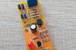
- 1 LED DIODE 5MM
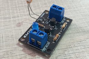
- 1 BLUE TERMINAL BLOCK 4 PINS
- 2 PUSH-BUTTONS
- 1PCB
FEATURES:
- VIN 24VDC -12VDC (IF WE CHANGE THE VOLTAGE IT WILL CHANGE R3 TO 1K )
- I MAX 0.020 A or 20 mA
- ISOLATED CONTROL SYSTEM
- PUSH-BUTTONS NO
- VOUT 220VAC
- OPTIMAL AND FUNCTIONAL CONTROL SYSTEM
ADVANTAGES:
- ISOLATED SYSTEM
- LOW CONSUMPTION IN THE CONTROL SYSTEM
- COMPACT SYSTEM
- EASY MAINTENANCE
JLCPCB
We thank JLCPCB for professional PCBs
Order your PCBs here
5PCBS AT $2
GERBER PCB:
https://mega.nz/file/jEAnyKTJ#vFj6t6YB-yaMHNf_yhgNuXVvKvPBmx3rEFv0QIMAIKE


 Jim Patchell