 Eric Hertz
Back Panel:
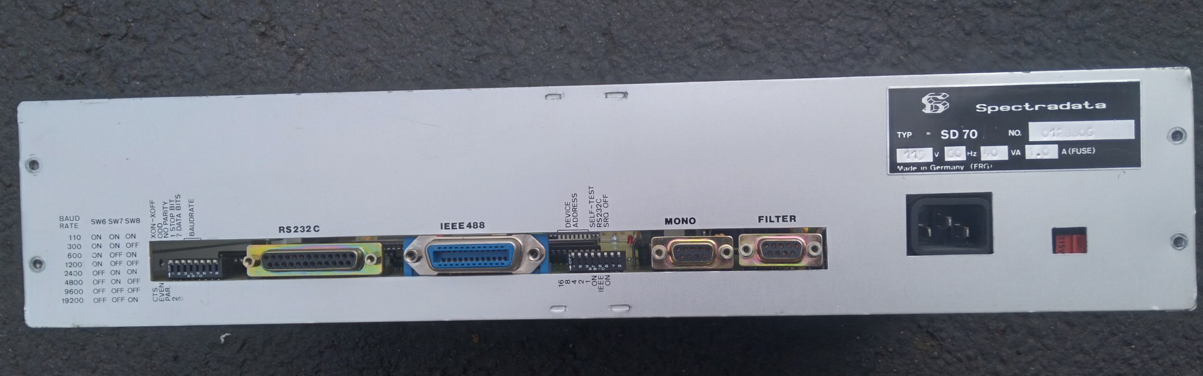
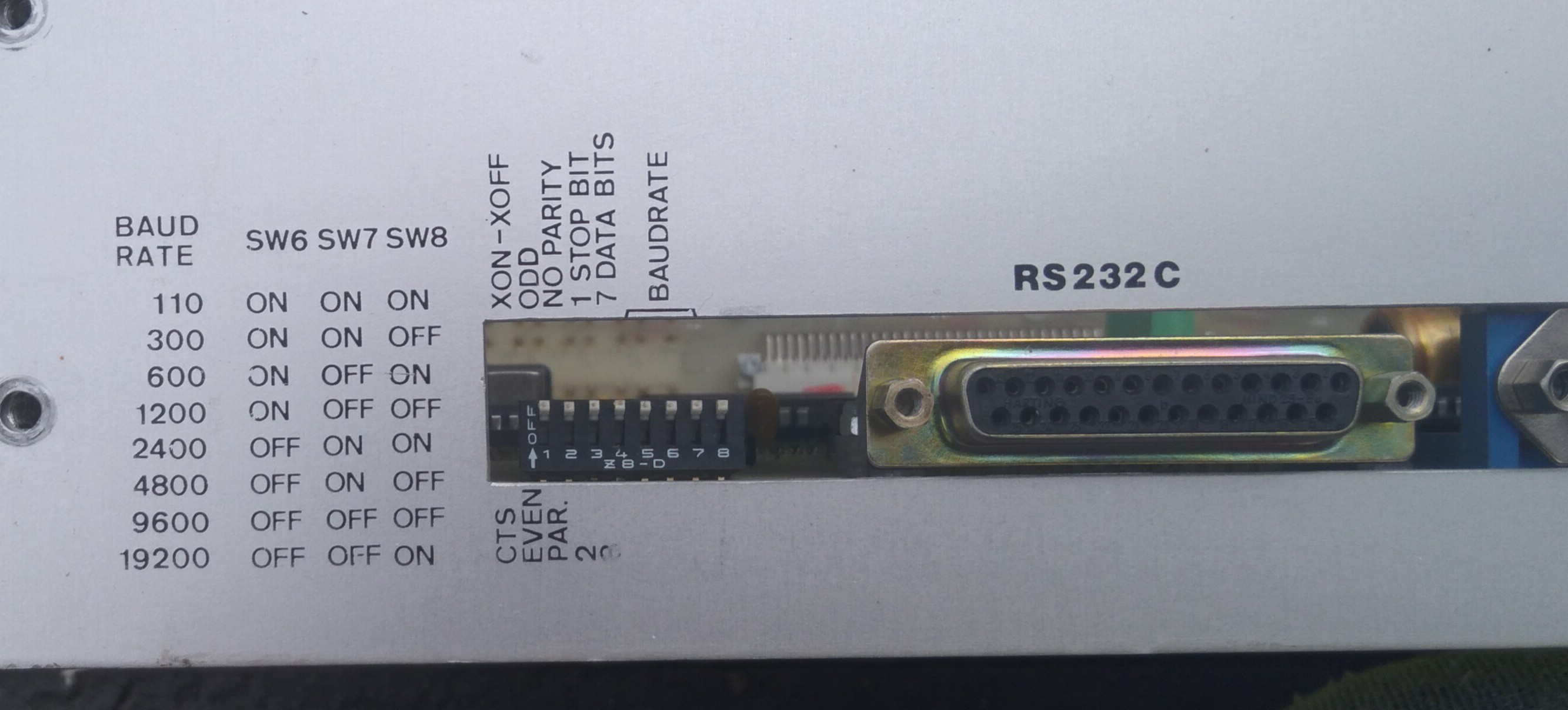
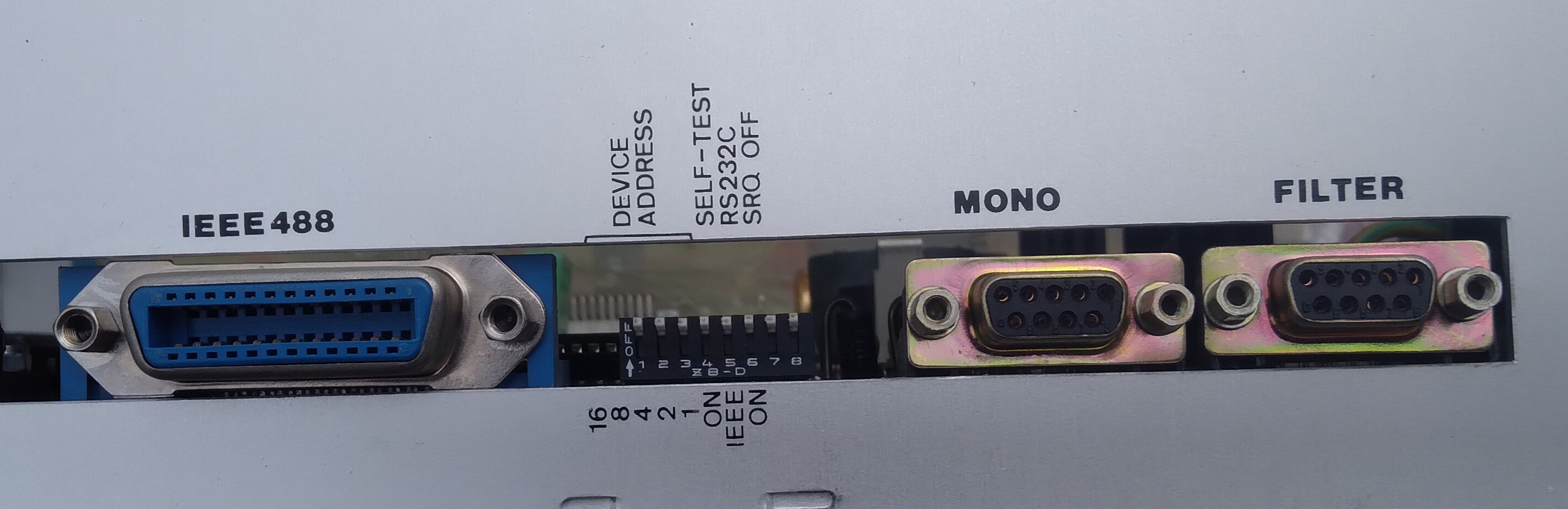
Heh, TBH, I hadn't looked closely at the switch settings. They're almost too informative! Lookie there, that switch next to the GPIB connector does more than just configure GPIB... There's a switch for choosing GPIB or RS232! I wonder if Self-Test isn't GPIB-related, after all. BRB.
(I vaguely recall SRQ being a GPIB signal, but it seems strange to locate just one GPIB-specific switch separate from the others. Why didn't I experiment?)
...Oh, right... Frankly I think the UI might be a bit buggy, or at the very least a bit obtuse.
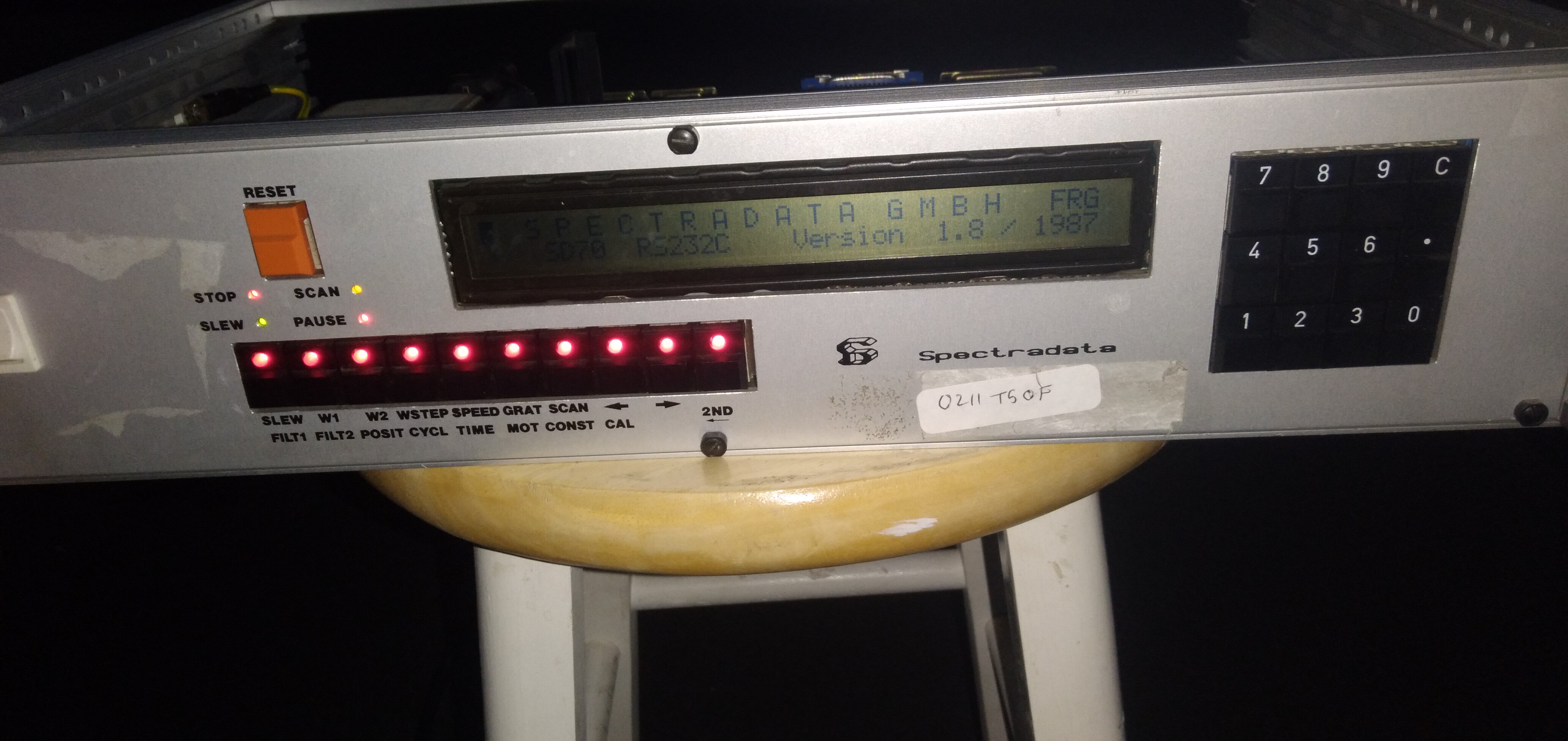
Self-Test, RS232/GPIB, and SRQ seem to have no effect on the boot process nor UI. It still says it's RS232 in the splash-screen. I suppose it's plausible there's an electrical/mechanical issue. But the UI, again, seems a bit buggy, in general.
For instance, right after boot you're greeted with:
W1=400.0000 1200 W2=500.0000
A:
Now, all the LEDs on pushbuttons are lit.
Enter a number, and press a selection, and it seems to respond, but doesn't always update the screen. EG "12345 Slew" gives "Invalid Slew Wavelength". "123 Slew" gives a blink of the Slew LED and turns the button LEDs off briefly. Then displays 123.0000 between W1 and W2. Makes sense... Arrow left/right increases/decreases that middle number. Great! Pressing "2nd" for the second row changes "A:" to "B:" and turns off the LED for the "2nd" button. Logical.
Play around a bit, now it displays A:, with all LEDs off (inverted?) Press 2nd a few times, and suddenly its LED seems to correspond again with A: or B: (A: = LED on).
I dunno. Also, pressing left/right arrows seems to pretty consistently modify the middle number, but that number seems not to be updated to whatever the arrows modify until after the arrows are pressed.
E.g. again, when you boot, that middle number is 1200. Pressing the arrows changes it immediately to ~0.0000 (interestingly, arrowing left past 0, it begins increasing, arrowing right past 0, it increases again!) OK, enter 123 W2, now the middle number and W2= shows 123.0000. Arrow left, Now the middle number jumps to 1.2500 and decreases from there.
(Oh, the SLEW LED blinks as the value changes! This *almost* makes sense!) BUT... GRAT... Gah, forget it... Too much. Too deep, with basically no idea what's going on.
Here's something: Theory goes it uses 48bit math. All the decimal values I've seen seem to increment in steps of .0125. And all the (rather large) integers seem to have a step size of 125.
Oh, hey... Now it's doing REALLY weird stuff. "5 W2" resulted in W2=55550000 I'd noticed switch-bounce before. It also *almost* looked like it said something about "invalid" really quickly, but "W2=55550000" was still the result.
Oh hey, I powered down and up again after typing that and now it says W2=555.5000.
Ooof. I dunno if any of this can be helpful. And, of course, it's entirely plausible my explanation of what I'm doing/seeing is questionable.
Here's where I, personally, say "eahhh, F it. Not like it's ever going to be used for what it was made for again... And even if I wanted to control some steppers in a similar way for something else, it'd probably be easier to just code the UI the way I understand, than to try to understand this..."
But, who knows. No sense in popping that ROM before I have anything to replace it with. And, Ziggurate29 always seems to find interesting treasures burried in such places.
@ziggurat29 apologies I'm losing track of probing/testing-requests. HaD's email-throttling makes it hard to keep track of messages :/
Discussions
Become a Hackaday.io Member
Create an account to leave a comment. Already have an account? Log In.
You've filled my plate with yesterday's bounty.
I have to do other things just now, but will be back at it, maybe PIO stuff tomorrow. One thing that vexes me about today's work is that there are some things that don't make sense as per manual. In particular CTC stuff. The code is clearly initializing the CTC in 'counter' mode, and I would have expected 'timer' mode for the BRG in particular. Moreover, the docs say that the prescaler is irrelevant for the counter mode, yet the code is clearly using it -- it has to for the 110 baud, it's too low and needs additional prescaling. Lastly, I cannot get the math to work out. It's off by a factor of like 8 or something. This bugs me because it will be important to know if/when we want to make custom firmware.
Which actually we are near ready to do. Serial will be our primary interface, I suspect, unless you're wanting to PDP it via those front switches and LEDs. Do you have an EPROM and an eraser/programmer? Or some drop in equivalent? (I don't know if there is a flash that could drop in.)
Incidentally, flicking the dip switch between rs232/gpib should definitely have changed the text on the display. The switch is tested and the text sent out very early in the boot process, and there is no visible code that does something like a 'fallback' if you don't have gpib install (which you don't).
Also, the 48-bit math is used /sometimes/ -- not for everything. I just casually stumbled across the routines when first started disassembling this so long ago. Seems like yesterday...
Are you sure? yes | no
Whoa, yeah, you've come a long way.
I coulda sworn I had the back panel in the original post, sorry about that. Definitely wasn't trying to withold it.
...
I just tried the GPIB/RS232 switch again... no change to the splash-screen. I also checked the voltage going into the LS240... Yep, definitely varies with the switch. Spose the 240 may not be doing its job.
Am at a loss, presently... getting dark, too.
...
I posted here, a screenshot during boot with GPIB selected... Still says RS232... I dunno how that might help.
...
LOL, you heard my ordeal reading that ROM... No promises regarding turnaround-time, I might have to figure out how to load Win98 without a floppy nor CD drive ;). But, I'll give it a go if you've got something you wanna test.
Running a serial terminal emulator... may be another such ordeal... "I'm working on it!" since december, heh. Nah, I'm sure I can figure something out...
Are you really that far along already?! Maybe I should make sure this serial even works, first... Maybe I'll plan that for tomorrow. Have you come across any sort of indication that this thing will even send anything (echo?) if I type at it, or if it's ascii or binary? No worries if you haven't I'll see what happens.
Are you sure? yes | no
I have not gotten that far along to know whether it will squirt out any data, or even it is expected to. Being as there is a GPIB/232 switch, it seems like those are alternative selections for connecting to the same whatever-it-is. And since GPIB is not used for interactive terminals, I would assume that the 232 as an alternative is similarly not being used as an interactive terminal.
Maybe I'll know more tomorrow.
My optimism about being ready to do custom firmware is not so much that we have comprehensive knowledge of what this unit can do, but that we have sufficient knowledge to make it do what we minimally need it to.
We understand the display thoroughly. We have a rudimentary understanding of the serial port. So, notionally, we could do an initial firmware that just prints 'hello world'. Then perhaps another that proves that we have the timers working right (too bad no scope for you right now, but we can figure out another way). Then perhaps just spewing out a fixed text over the 232 and verify it can be received correctly.
So, essentially, a board bring-up. Once we have basic IO capability working, then further experiments become easier.
But we don't have to do any of that if you don't want to, or if you're not prepared to. This is your project and it's supposed to be fun. The custom firmware thing was a detour from what you were originally planning, anyway. So I've already derailed you, lol! But I do think it will be fun. Or frustrating -- either one.
Are you sure? yes | no
Ohhh... gotcha! For some reason I guess I was imagining you had plans to jump right into serial and got a bit overwhelmed thinking of all the potential hurdles debugging that. Of course, start simpler, duh. Yeah, I mean, if you have enough info to start with the LCD, or even an LED, that'd at least give us some idea it's doing what we expect each step along the way... Buttons may be a pain, being, it looks, scanned in a matrix. There are also LEDs which, I'm guessing at least one or two are driven directly (not scanned). I can definitely probe things out there, too, if it would help.
I suppose, now that I think of it, you'd be capable of even reusing some of their known-functional code, almost like libraries, even in a completely different ROM. Wild concept I hadn't really thunk before.
Scoping isn't impossible, nor really that difficult; it just takes some planning and cooperation from the weather...
And, nah, I definitely planned custom firmware some day, just had no idea we'd get there this quick! I guess, now that you put it that way, there's really no reason I should've thought otherwise. And there's no reason at all that I might prefer it that way.
Let's do this!
I am, however, likely to crash through most of tomorrow, which is now today. I'm up late enough for bacon before bed, hah!
Are you sure? yes | no
Get some rest. Or do what you like! If you want to peruse the data sheet, perhaps you can lend a cerebral cortex on my bit rate problem.
CTC channel 0 is used as the BRG into the DART. This is known. The system clock is 4.9152 MHz. So the CTC should be dividing down the system clock (or some division thereof, but never a multiple) to a rate into the DART that will result in the desired serial bit rate.
DART is configured for a BRG divisor of 32. It is configured via list at 2A0D of 9 values that are copied to RAM and then blasted into port 08h. The salient one is the 84h which selects the x32 clock. It's useful to note that these are first copied to RAM, because they are later tweaked according to DIP switches before blasting to the DART.
The bit rate divisors are at 2A05. They are indexed by the lowest three DIP switches. These are loaded into the 'time constant' of the CTC; so another divisor.
So far so good conceptually, but this is where things break down in a few ways:
1) the CTC is configured in 'counter' mode and not 'timer' mode as I would expect. This is done at 191f. Perhaps my expectations are invalid. Either way, the datasheet says the prescaler is irrelevant in counter mode.
2) I am pretty sure there is a bug at 1a13h. Here they are attempting to tweak the CTC prescaler (which remember is irrelevant in this mode) by setting bit 5. That switches from the default x16 to x256. The reason they do this is for 110 bps. It's so slow that they need additional prescaling. And the math works out that the extra x16 prescaling would result in the divisor of 174. However, they aren't flipping bit 5 of the CTC. They are flipping bit 5 of wreg 4 of the DART! Which the docs say is ignored. And even if they were flipping bit 5 of the CTC, it shouldn't matter because the prescaler is ignored in counter mode!
So I think 110 bps never worked. It's possible that it was never discovered because who uses such a low bit rate, even in the 80s. (there's some other "interesting" code elsewhere that I'll point out separately)
OK, handwaving past my befuddlement over 'counter' vs 'timer' and the special case of 110 bps, either way the net divisor has to come from the system clock frequency. So treating the CTC bit as a black box and working to the middle, we can work an example. I'll arbitrarily pick 4800 bps. That has a divisor value of '8' as per 2a0ah. So:
4800 x 32 x 8 = 1.2288 MHz
4.9152 / 1.2288 = 4
The CTC doesn't have a prescaler of 4. It has one of 16 or 256, but moreover the prescaler is irrelevant in counter mode. And we're definitely in counter mode.
So I think with my surprise about the CTC config and this math that my assumption about the electrical configuration is wrong. Perhaps there is externally a divide-by-4 that is fed into the CLK/TRG input. I can't see that via code, that would require looking at the schematic. And I don't see any 7474s or whatnot in your board shots that would be an obvious /4 prospect, so I'm at a loss.
If you do want to read the datasheet, let me give you a little leg up on how these peripheral chips work, because it's a little different than other stuff. In other stuff you usually have enough address lines to select the internal register you want to write to. Straightforward. In the Z80 peripherals, its more of a state machine. You write to a port specifying the register you want to reference in the /subsequent/ write to that same port. It's a little disorienting -- at least to me -- but I can only assume that this is a port address space conservation maneuver.
So, if you want to plunder the board, it would be interesting to see if there is a couple flipflops or something that is doing an external divide-by-4 into the CTC CLK/TRG0 (pin 23). If you had a scope, or even a frequency counter function on your meter, it would be interesting to see the actual freq at the various pins under at least one bit rate as a sanity check. It would be extra interesting to see what happens under the '110' setting, because by my calculations that should result actually in 220 bps, and the BRG to the DART would be 7.062 KHz.
Lastly, it would be interesting to see if the BRG lines are also connected to the DART port B. To save you some time, port A has separate RX and TX clocks, but I'm sure they are tied together in this application. port B has them internally tied together. So here are the pins: RXCa 13, TXCa 14, RXTXCb 27. Continuity between all?
It might be neat to be able to use the second DART port. To paraphrase S.R. Hadden in "Contact": First rule in peripheral support: why use half of it when you can go ahead and gratuitously use both halves? But if not, then no biggie. And the SIP resistor network on the back side of the board gives one pause. What is /that/ for?
Are you sure? yes | no
BTW, I did, actually, see a FLASH chip in my programmer's box, which I used briefly (before burning an EPROM) during #Improbable AVR -> 8088 substitution for PC/XT ...
Guess which one it just happens to be... I'll give you a hint, it's a PLCC that I had to make a DIP adapter for.
I'll give you another hint, it's at least a few times larger than PC/XT ROM sockets supported (which meant my adapter has jumpers for selecting different firmwares.)
(How handy will that be for this!)
I must get bacon. Then we'll see whether I doze through the day or get a fourth wind. Would you believe I only had a 1/4 caf cup of coffee, and at the start of my day?
Are you sure? yes | no
Whelp, I figured on doing serial today, but I wound-up snagging two unused shelf-brackets when I pulled out the box of RS232 cables!
The board between em is bowed quite a bit, but I'm pretty sure it'll hold up to the light (and easily crushed, so couldn't be stacked upon) boxes I put up there. So, holy moly, I just cleared a LOT of space. If I'm smart about it, printers, programmers, etc. could be sat back there atop the now-flat-topped sturdy-stacks of boxes. This could be revolutionary, or it could wind-up piled-up and unusable again, We'll see!
Despite the uncovering of many deeply-burried treasures, including the box of serial cables, would you believe I didn't find even one DB-9 to DB-25? I know I had at least a few, so they must've wisely been "organized" into "one basket" burried somewhere else.
I did, however, find (...and lose?! where'd it go?!) one of those breakout boxes I'd never thought I'd use, since the ol' soldering iron was just a flip of a switch away. This could be handy, 'bout now.
Sorry to leave you hanging on the CTC weirdness! I guess I figured serial comms are definitely in the near future, so it couldn't hurt to at least see *if* I can see if those baudrate switches actually are labelled correctly, and in the process be prepped for the big test.
Holy moly, I could set up the compy, programmer, and maybe more semi-permanently atop those storage totes, right there!
Are you sure? yes | no
Here's something weird-to-me... (as I debate bacon from the gas station before bed, again). The crystal has a parallel-resistor. In the ones-of-kilo-ohms, as I recall... I mean, it seems very unlikely, but equally unusual... could it somehow slow the crystal, such that your math works out?
Are you sure? yes | no
at your leisure on CTC sanity checking. I had a fever dream that perhaps they used another channel as a prescaler, which would be a waste, but that one is set up divide-by-two, not 4. I don't really know where that channel goes, so there could be some probing in the future. It's not critical to know.
I don't know what to say about the resistor; I've not seen that done before, but I would suspect that simply reduces Q and not the resonant frequency. And that would be a hell of a pull to drop it by 4 (and then of course the whole system would be dropped by 4; boo!). Maybe it helps startup be more reliable, dunno.
With regards to serial, yes, I should a zillion of those now, but where did they go?
Don't forget you may also need a NULL modem. I don't know if it's wired DTE or DCE.
In other news, I did at length figure out PIO stuff, at least. It took all day. This poly-whacking port scheme of the Z80 peripherals threw me off a bit and the datasheets have the details spread out in text like a Sumerian myth instead of consolidated into a graphic format that my walnut-sized dinosaur brain can grok. But it is accomplished.
In the course of that, I have been using your nomenclature since we don't have a silkscreen, and have been calling the devices "pio0bp" for the one you call #0 near the back panel, and "pio1fp" for the one near the front panel. Both can generate interrupts. I am guessing we'll be less interested in the back panel since I'm suspecting that goes to the spectroscopy equipment we do not have (only you can know), and the front panel will be of interest because it probably goes to switches and whatnot.
So I'm going to look into FP pio stuff today after I take one last look at DART interrupts.
Then perhaps it will be time for a new post, because this thread is getting long and it's far off the topic of photos, lol.
Are you sure? yes | no
Holy Moly, we have serial comms... I'll start a new log and edit it as i go along with new discoveries...
Are you sure? yes | no