 Chance Reimer
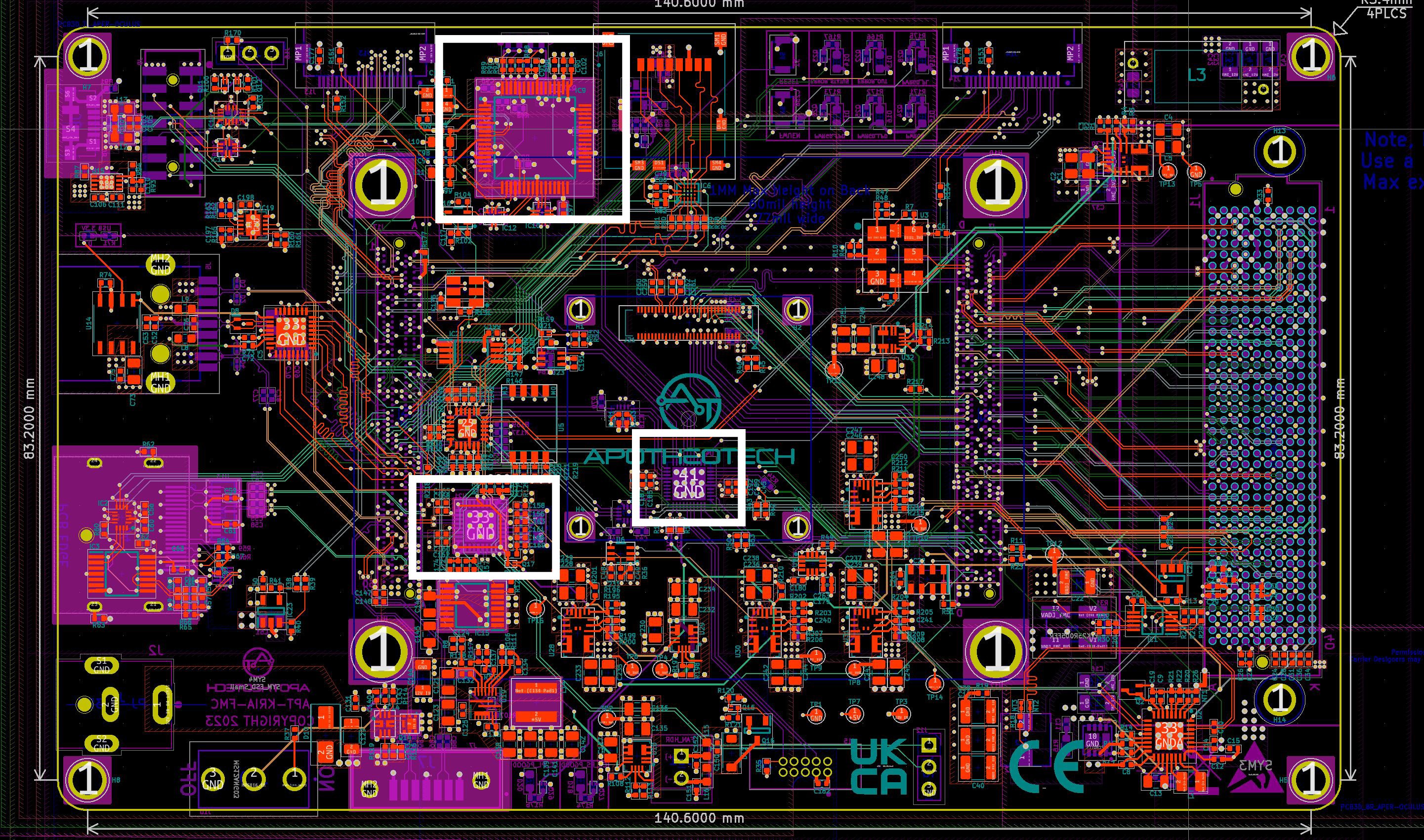
Now somewhat confident this board won't explode in my face and singe my hot-cheeto encrusted stubble, I move on to the making this shiny paperweight actually usable. There are 3 chips of interest on the board that we would like to program to enable complete functionality of the Aper-Oculus, and these include, the FTDI 4232H, the PIC18LF47K42, and the SI5332 clock generator.
The only real unknown when I started this project was how to get the FTDI chip working as expected, as the USB to JTAG program was closely guarded. I was planning to rip from the Xilinx Kria SOM development board EEPROMs, but thankfully I took so long with this project that Xilinx released a tool called program_ftdi that does this for you without all the hassle of using the FT_PROG.
The steps to program the FTDI EEPROM are amazingly simple:
- If using the Aper-Oculus, make sure that the Kria SOM is plugged in correctly (read the above section).
- Plug in the micro-USB connector to the host PC (ensure that the USB Vbus has no shorts before doing this so you don't damage your PC's USB port).
- Open Vivado 2022.2 (I'm not actually sure which version this was supported, but this is the one I'm using)
- type into the Tcl Console, "program_ftdi -write -ftdi FT2232H -serial 0ABC01 -vendor "my vendor co" -board "my board" -desc "my product desc". Of note, the -vendor, -board, and -desc must all be lower case or you'll receive an error.
- Profit.
Once the FTDI chip is programmed, you will be able to autodetect the board in Vivado reliably, and program with it. I'm still unable to get UART up on Port B of the FT4232H device, which is perplexing, but once my Oscilloscope comes in, I will probe the bus to try to figure out what the issues are.
Next is the PIC on the board for power control. This needs to comply with the power up sequence specified in the KV260 Vision AI Starter Guide (UG1089) as this was the only place that I found that describes the functionality of the power up sequence. 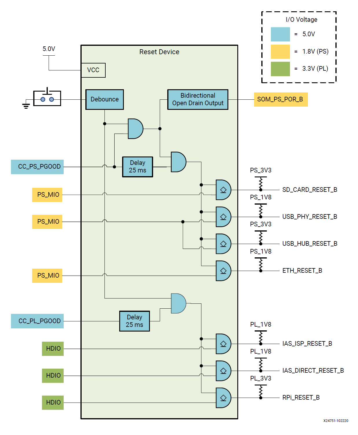
To program your own, you'll need a programmer converter, specifically the AC102015, using the Cortex JTAG/SWD header (J4) and connect it to J15 on the board. Next you'll need a suitable PIC programmer, I am using the ICD4.
Steps to program are:
- Plug in the AC102015 J4 to J15
- Plug the AC102015 to ICD4
- Power on Aper-Oculus (with or without Kria SOM applied)
- Power on ICD4
- Program and flash from MPLabs
I'd recommend checking all PIC code using MPLab's debugger, or by probing resistors for resets. If the code is incorrect and asserts PS_POR_B forever, the FPGA will not be able to boot, so be careful troubleshooting.
The PS side of the FPGA requires 3 clocks to support all the interfaces that I have broken out on the Aper-Oculus. The schematic can be found on the "PS_Clocks.kicad_sch" page, and basically copies the same SI5332 layout that was on the original Kria Carrier board. To program this part, you must have Sky Work's Clock Builder Pro installed. I also have this project in the Github repository, in ~/SW/SI5332_Clock_builder. To program you must have the Sky Works programmer, and you should connect pins 1, 3 and 7 to the Aper-Oculus J12.
To program this device you must:
- Connect the appropriate programmer to Aper-Oculus
- Power on Aper-Oculus
- Power on programmer
- In Clock Builder, select (program NVM), which will take the place of (No EVB Present) when Programmer is powered up and plugged into computer.
- The default I2C address of the chip is 0x6A, but be careful with your project as you can accidentally change this. I don't recommend naive users to program the NVM of the SI5332 on the Aper-Oculus
I've programmed the 4 boards with the above, and now must test the other ports on the board work as expected. RS232 will be debugged after all interfaces are brought up working with known good test designs. Thanks for reading!
Discussions
Become a Hackaday.io Member
Create an account to leave a comment. Already have an account? Log In.