 Chance Reimer
The board's peripheral ICs are programmed, and voltages look good. It is now time to summon the unholy color bars, and truly bless the Omnissiah with its glory. We'll be doing this using a Xilinx Block Diagram, leveraging the Test Pattern Generator, AXI4S to Video Out, and Xilinx's own PS-GTR Displayport IP Block.
The high level block diagram schematic looks like this:
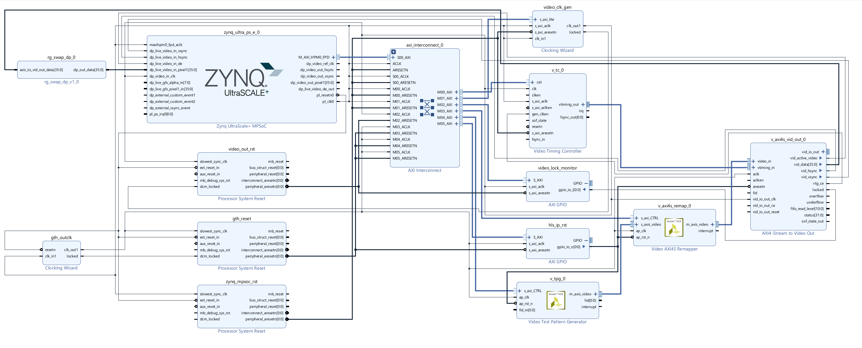
The above uses the video axi4s remap for no other reason than a previously misguided attempt to only use 1 pixel per clock while attempting to design a CoaXPress Host output. You could remove the axis remap without issue, and plug the TPG directly into the video for axi4s out. I noticed that the axi4s to video out to the PS-GTR has strange color flipping, which I fixed with a quickly added IP to swap the correct bits. These are both added in the github, using a project creation TCL file, and by pulling the RG_Swap IP in the same top directory. Run the TCL files by using:
source TPG_3840_Test.tcl
If you're using windows, I recommend pulling the files to the C:/ directory, as Vivado can generate some impressively long file paths. If you're using Linux, do whatever you want.
The C code to program the project should be opened in Xilinx Vitis. To create this project you should create an platform project, import the exported hardware file from Vivado, and then follow the prompts. After this is done, create an empty application project and import the software files found in the githubs SW directory.
With both of these programmed, you can actually program the Aper-Oculus directly from Vitis, via the FT4232H, regardless of the mode pins. It ends up looking like this:
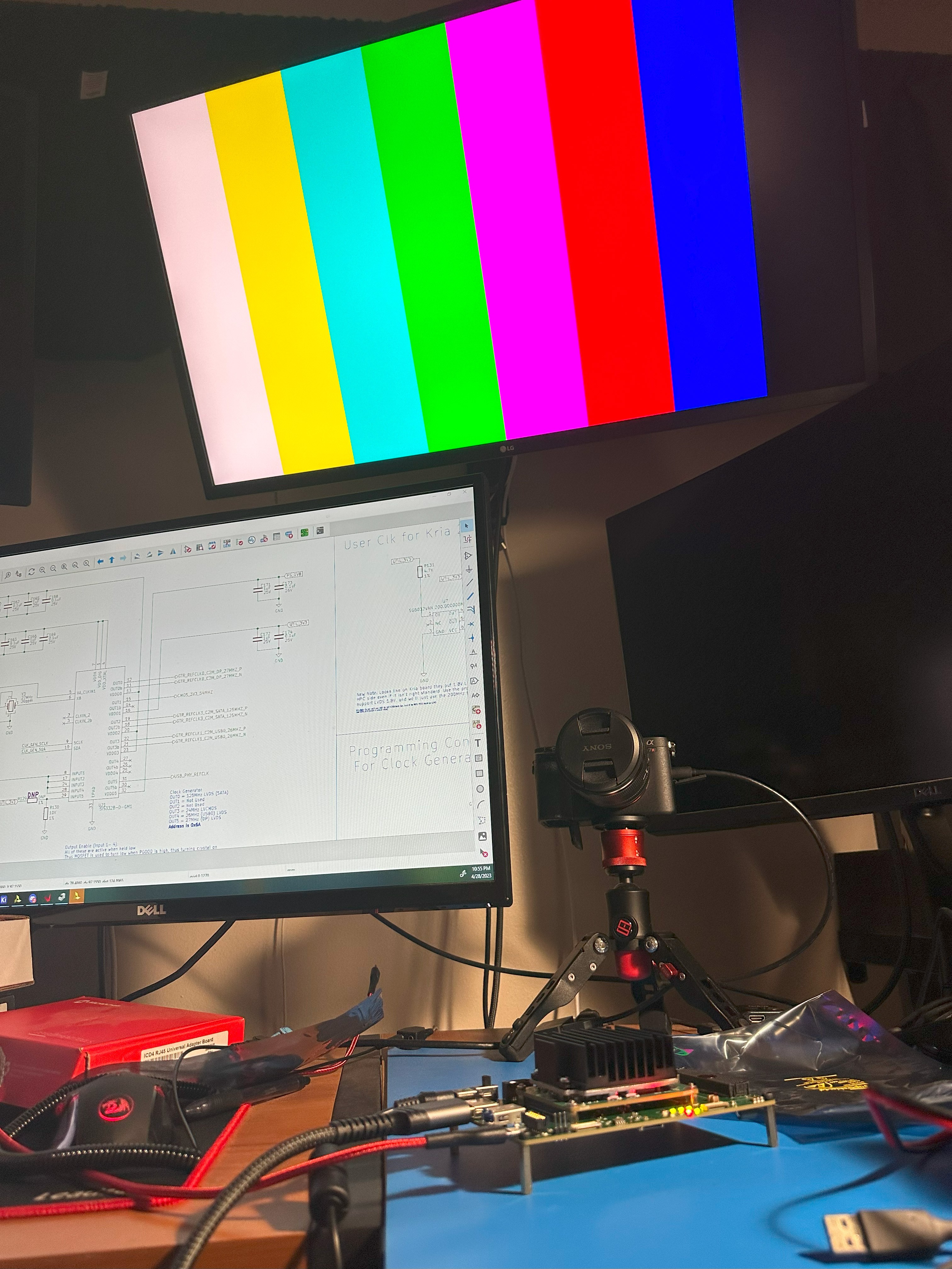
with a bouncing box slowly going across the screen. If the FT4232 UART was working correctly, I would be able to change the TPG pattern via UART, using a menu based callback configuration, seen on many of Xilinx's Example Designs. Again, I'll debug the UART later.
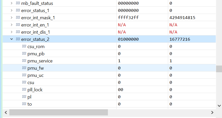
One strange finding from programming the Kria is the ERROR_OUT status from PMU. To find the error status registers, you must be in debug mode, and select the APU in the debug window.

Then, scroll down to find the error_status registers, 1 and 2. More information can be found about them in UG1085. I'm not sure why pmu_service is flagging as an error. I'm not even really sure why it cannot access ROM? What ROM? Is this possibly something referencing the EEPROM on the board? I'll investigate more later to try to figure this out. If anyone knows, it'd be a huge help, and turning off this obnoxious red led.
 The next update will be proving the CoaXPress Host to a CXP camera using my FMC board. See you there!
Discussions
Become a Hackaday.io Member
Create an account to leave a comment. Already have an account? Log In.