sandy
sandyHow-to-make-Arduino-based-thread-winding-machine

Hello friends in this video I have made an automatic thread winding machine using Arduino.
775 DC motor used to run the spool and stepper motor is used to slide thread guide mechanism.
I have also used one rotary encoder to calculate the length of thread wind to the spool.
I have used one Nextion HMI from where User can give Input like how long thread need to be wind on spool in meter.
After winding that exact length of thread on spool both motor will stop automatically.
COMPONENT USED
- Arduino Nano
- Multipurpose custom PCB
- 775 DC motor
- A4988 Stepper driver
- Nema 17 Stepper motors
- Timing pulley
- Timing belt
- Linear rails
- 3D printed parts
- Optical rotary Encoder
- Some hardware
- Nextion HMI


First of all I have prepare the base of machine using 12mm wooden ply. And made the 8mm hole
At the four corner of the wooden sheet.
This 8mm hole is used to install the rubber legs.
I also made the all corner round using my bench sander machine.

I then made the frame of 20x20 Alu. extrusion profile.
This frame is used to attach all the components of the machine.
The main reason to use 20x20 alu. Profile is its very easy to attach and detach the components by just using the T nuts.


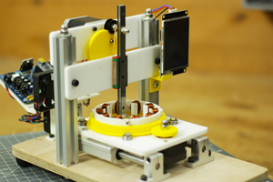
Then I use my home made CNC router to cut the 6mm Acrylic.
I made the to parts to hold the spool.
There is a hole in acrylic part to place the bearing in it, then a SS shaft pass through it.
One end of this shaft is attached with timing pulley,
Then I attached both acrylic part with 20x20 Alu. Profile in front of each other.


Then I place a 775 DC motor on the one of the acrylic part. and secure it with the help of M4x10mm Allen bolt.
Then I connect timing pulley on the both end of shaft and DC motor shaft.
I connect both timing pulley with the help if timing belt.


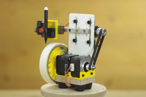
Then I design a 3D part so that I can install linear axis on it and, 8mm lead screw
I have place 8mm ID bearing on both 3D printed parts so that we can pass 8mm lead screw through it so that lead screw can rotate easily.
I have used 9mm linear bearing for left and right movement. this will used as thread guider for the machine.


Then I place 8mm timing pulley on the 8mm lead screw and place a Nema 17 stepper motor to run this lead screw.
I connected the lead screw and nema 17 stepper motor with the help of timing pulley.


Here I have used a optical rotary encoder to count the length of thread wind to the spool.
I used Orange 400 PPR 2-Phase Incremental Optical Rotary Encoder
A rotary encoder is a type of position sensor which is used for determining the angular position of a rotating shaft.
It generates an electrical signal, either analog or digital, according to the rotational movement.
Orange 600 PPR Incremental Optical Rotary Encoder is a hi-resolution optical encoder with quadrature outputs for increment counting.
It will give 2400 transitions per rotation between outputs A and B. A quadrature decoder is required to convert the pulses to an up count. The Encoder is built to Industrial grade.


For this project I have used my multipurpose PCB this PCB can be used for so many projects.
I have design circuit and PCB in easyEDA and ordered PCB from JLCPCB
JLCPCB are the world leader in PCB manufacturing there PCB production rates are very much affordable and they have world class PCB production unit results fast PCB production.
I have provided the link of circuit design so that you can modify it as per your need if you need to change anything.


At last I have used Nextion HMI for user interface, we can give commands like how long thread need to wind and start stop the machine.
In this way the construction of the arduino based thread winding machine is completed.


 DIY GUY Chris
 Mrinnovative