 ElectroBoy
I am working on a 2.4ghz radio receiver module, NRF24L01 is the best and cheapest module which supports a long range along with high data speed in tasks like remote sensing. These modules are very easily available to anyone and very difficult to troubleshoot. Today we will discuss the problems with these modules along with basic circuit of transmitter and receiver.
It is not easy to make a simple circuit, because these modules are not breadboard friendly. And long SPI connection may produce some noise. There is one method to use these modules with microcontroller like Arduino is to make a dedicated shield with power line filters. These PCB shields are sponsored by JLCPCB, one of leading PCB manufacturer. Get your amazing PCB 5pieces for $2.
NRF14L01 and Features:
- Worldwide 2.4GHz ISM band operation
- Up to 2Mbps on air data rate
- Ultra-low power operation
- 11.3mA TX at 0dBm output power
- 12.3mA RX at 2Mbps air data rate
- 900nA in power down
- 22µA in standby
- 1.9 to 3.6V supply range
- ±60ppm 16MHz crystal
Simple circuit basics:
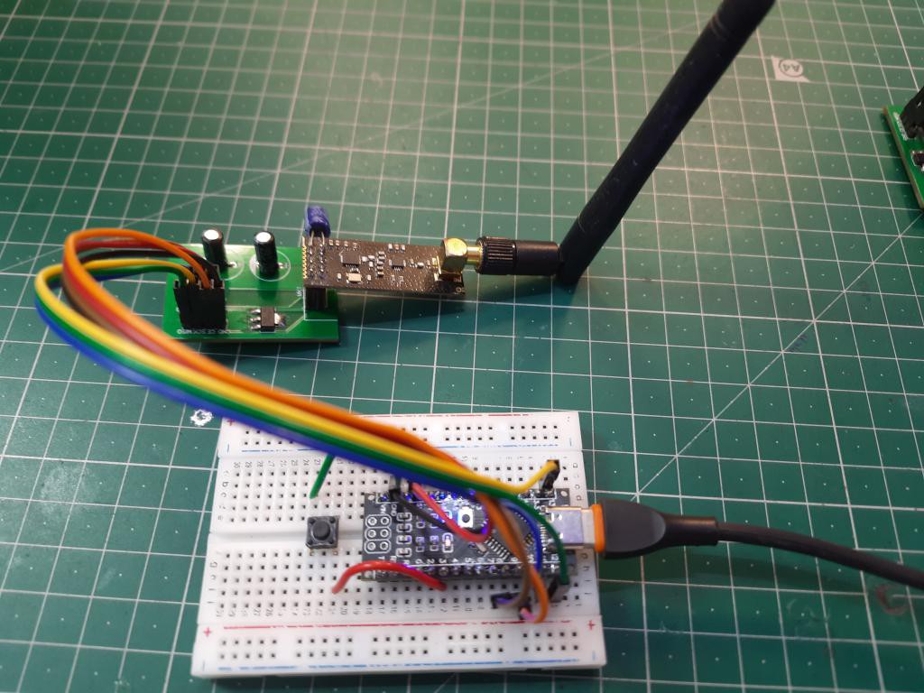
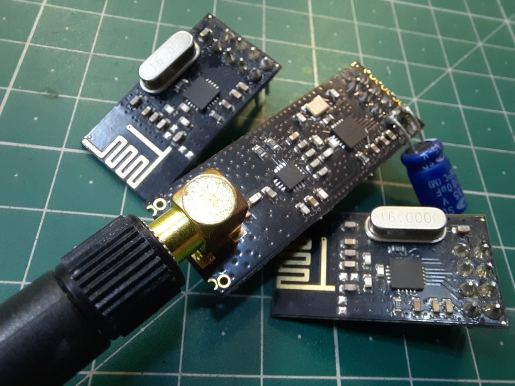
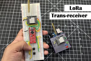
I have two modules, one with long antenna and internal amplifier and other one is simple. As for test purpose, we will use a simple blink code to make our project working. The Led will only blink at the receiver end if triggered from transmitter.
Components required:
1) Arduino NANO
2) NRF24L01 modules
3) Tactile button
4) Led with resistor
5) Shield for NRF24L01
6) Connecting wires
7) Battery
Circuit diagram:
Receiver and transmitter wiring is depended on Arduino Digital pins mentioned in code. Chip enable and chip not enable connections are goes to digital pins 9 and 8 respectively. Chip not enable signal is a logic low signal and always remains at high except when you are sending the device an SPI command or getting data on the SPI bus from the chip. SPI communication is very basic, just connect the MOSI to D11, MISO to D12 and SCK to D13. We are not using any interrupt to do this so no need of IRQ pin here.
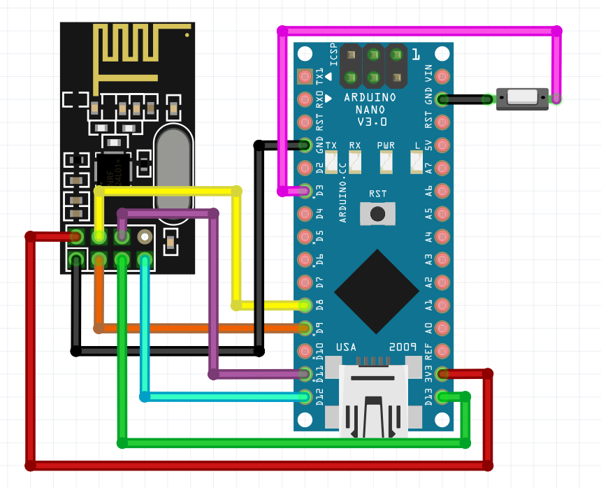
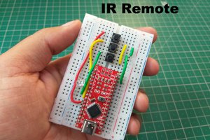
In the transmitter section the D3 pin is used as input, which is made input pullup and activated when connected to ground. So, a tactile button is placed to make it more responsive.
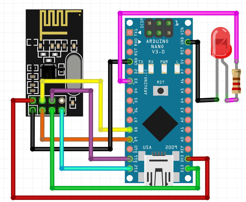
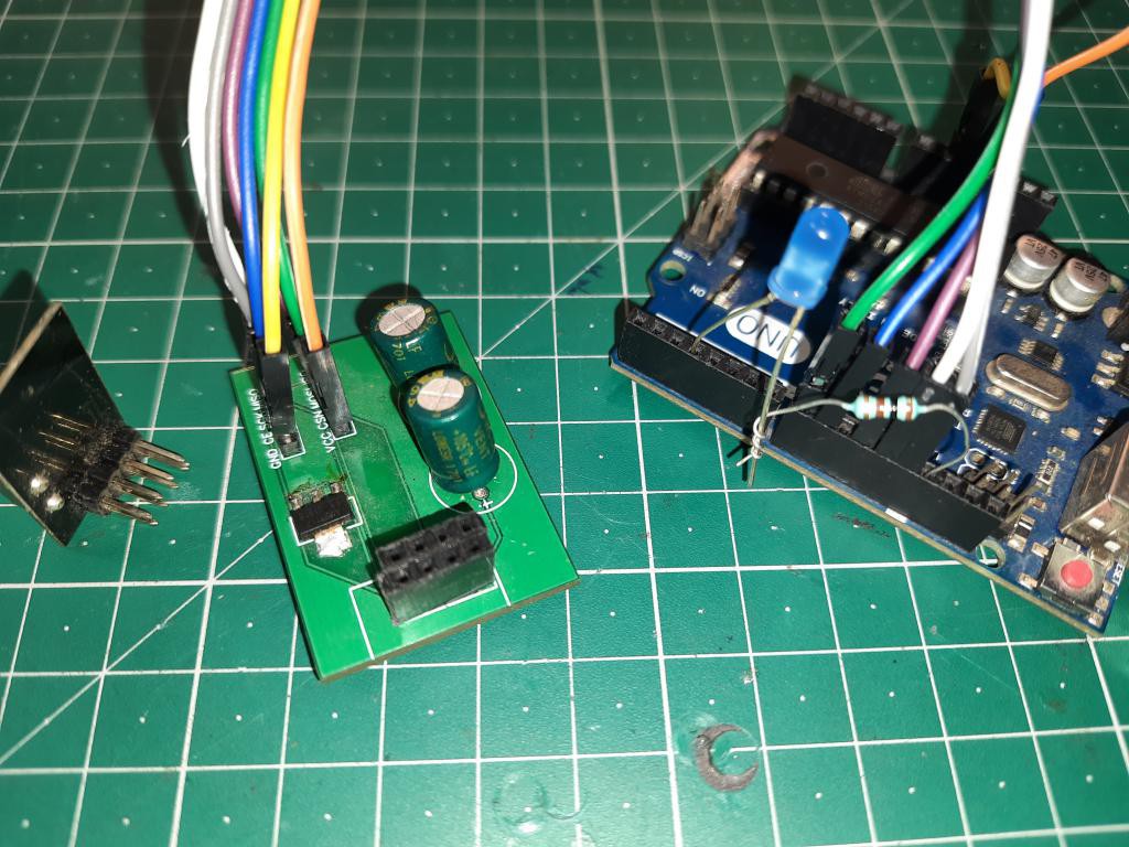
In the receiver section the D3 is defined as output, a LED is connected to the pin with 220ohms resistor. Which remains high if the receiver doesn’t find any transmitter and after that it can be controlled using the tactile button.
These NRF4L01 modules work on 3.3volts and need a maximum of 30Ma. Here I am using a pcb adaptor the files can be downloaded from here. Have a look on troubleshooting section at the end of this article, which will give you more brief designing tips.
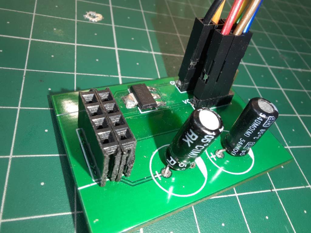
PCB for NRF shield:
I made a shield to reduce the overall noise, I added two electrolytic capacitors for power filtering and 2 ceramic filters for low frequency blocking. To make the module breadboard friendly the Pin headers are mounted in one direction.
I am using JLCPCB pcb assembly service for a long time, I made many projects and the quality they provide in this price range is really amazing. Sign-up to JLCPCB to get free coupons of $54 now. Visit JLCPCB to try other services like SMT assembly, PCBA, stencil and 3D- printing. 2
Code for transmitter:
#include <SPI.h>
#include <nRF24L01.h>
#include <RF24.h>

#define buttonPin1 3

int buttonState1 = 0;
RF24 radio(9, 8); // CE, CSN

const byte address[6] = "00002";

void setup() {
  pinMode(buttonPin1, INPUT_PULLUP);
  Serial.begin(9600);
  radio.begin();
  radio.openWritingPipe(address);
  radio.setPALevel(RF24_PA_MIN);
  radio.stopListening();
}
void loop() {
  buttonState1 = digitalRead(buttonPin1);

  if (buttonState1 == 1)
  {
    buttonState1 = 1;
  }
  else  if (buttonState1 == 0)
  {
    buttonState1 = 0;
  }

  Serial.print(buttonState1);
  radio.write(&buttonState1, sizeof(buttonState1));
}
Code for receiver:
#include <SPI.h>
#include <nRF24L01.h>
#include <RF24.h>

#define led1 3


int buttonState = 0;

RF24 radio(9, 8); // CE, CSN
const byte address[6] = "00002";

void setup...
Read more »
 Lithium ION
 Julien