Colin Maykish
-
RC 2022/10 Day 6: Flounder Interrupted
10/07/2022 at 03:16 • 0 commentsASCI Clock Generation
I've been cheating a little in the way I use the Z180's onboard serial ports, specifically the baud rate generation. In a typical application, the baud rate is generated in the CPU as some factor of the system clock PHI. It's a little tricky to understand the exact combination of register bits required to make this happen, so my "cheat" was to not to use it at all. Instead, it's possible to provide a second oscillator to the CPU along with the system clock. This oscillator can be used directly as the baudrate (divided by 16). In my case, an oscillator of 1.8432 MHz on the CKA pin will give a baudrate of 115,200 without any additional software configuration. This is fine, but it does mean a second oscillator is required and the baudrate is not easily adjustable. I figured it was time to generate the ASCI clock properly and eliminate the extra hardware.
Somewhat annoyingly, the internal clock generators still require a magic oscillator frequency, but it's more flexible in which magic oscillator you pick. 18.432 MHz (yes, 10x the other one) seems like the most common choice since it's close to the speed limit for the 20 MHz Z180 variant and the 33 MHz variant can apparently handle doubling it to 36ish MHz without issue.
To actually generate an ASCI clock from the system clock, there are a few key registers. I'll outline my configuration as an example:
CCR = 0x00: This sets PHI to 1/2 of CLK, i.e. 9.216 MHz
ASEXT0 = 0x00: Set the X1 and BRG mode bits to 0
CNTLB0 = 0b00100001: Set the PS bit to 1 for to /30, DR bit to 0 for /16 and SS to 0b001 for /2
All of that should come out to: 18.432 MHz / 2 / 30 / 16 / 2 = 9600 baud. To adjust the baud rate, these factors can be scaled up or down as necessary.
Periodic System Timer
The next thing I needed to tackle was interrupts. I've implemented interrupts on the 6502 and the 68000. The Z180 is somewhere in the middle in terms of complexity. There are three interrupt modes that the CPU can be in at any one time. Mode 0 and 1 seem to be mostly for compatibility with older or non-Z80 specific peripherals. Mode 2 is the focus today: vectored interrupts.
Similar to the 68000, when a mode 2 interrupt is triggered, the CPU basically asks the peripheral for the address of its interrupt handler and then jumps there to execute the interrupt service routine. The Z180 has four external interrupt pins, but I've chosen to ignore those for now (they're actually disabled entirely) and focus on using the internal countdown timers to generate a periodic interrupt.
Conceptually, this means I need to set up the timer peripheral, write an interrupt service routine somewhere in code, link the timer interrupt with the ISR, and then enable interrupts. In reality, this was a lot harder than I expected. The Z180 manuals and documentation I could find were light on details for actually implementing something like this and the z88dk wiki is tough to follow when you're using custom hardware and not one of their supported systems. I'm confident there are better and more robust ways to implement vectored interrupts under the z88dk umbrella, but my first goal is always to get anything working and then iterate. In that spirit, here's the bare minimum code I set up to get a periodic timer interrupt running:
    org $0000
    jp init

; Block 0x00 - 0xFF is reserved for other interrupt modes

; Block 0x100 - 0x1FF is reserved for interrupt vector map

ALIGN 0x104

    defw asm_isr_prt0       ; Put the address of the PRT0 timer ISR at the right vector

; Code definition starts at 0x200

ALIGN 0x200

init:
    di
    im 2

    ld sp, $FFFF            ; Set stack pointer to top of RAM

    ld a, $01
    ld I, a                 ; Set base interrupt vector to 0x100

    EXTERN _main
    call _main              ; Jump to C code main()

asm_isr_prt0:               ; PRT0 timer interrupt handler
    di                      ; disable interrupts
    exx                     ; swap to shadow registers
    EXTERN _ISR_prt0
    call _ISR_prt0          ; call the C code handler for this interrupt
    exx                     ; swap the shadow registers back
    ei                      ; enable interrupts again
    reti
First of all, the vector table needs to exist somewhere in memory. On boot, it's set to 0x00, but I changed it to 0x100 in ROM by writing 0x01 to the I register (the high byte of the interrupt base vector). In this vector table are pointers to the various interrupt handlers. In this case only the PRT0 timer has a handler mapped.
This PRT0 timer interrupt has a hardwired interrupt vector of 0x04 (defined in the Z180 manual), so the vector table base plus this offset gives an address of 0x104. In other words, when the PRT0 interrupt fires, the CPU will look up the 16 bit address stored in 0x104 and jump to it, expecting an ISR to exist at that memory location.
That ISR does exist and it's called asm_isr_prt0. This ISR can do pretty much anything, but it should immediately disable further interrupts and re-enable them right before returning. In my case, I've chosen to call a C function to do the bulk of the interrupt handling logic there. It looks like this:
void ISR_prt0()
{
    // Clear the interrupt by reading these registers
    uint8_t a = z180_inp(TCR);
    uint8_t b = z180_inp(TMDR0L);

    asci0_putc('x');
}
Not much to look at, but it's a proof-of-concept for handling interrupts in C. Critically, in the case of the PRT interrupts, TCR and TMDRnL have to be read in order to the clear the interrupt. Without doing this, the interrupt will run in a tight loop forever, blocking out any other code from running. I could not find this anywhere in the Z180 manual, but eventually dug deep enough into the z88dk source that I found something similar.
Finally, the PRT has to be given a counter value and started:
// Load timer 0 with 0x1000 starting value  (roughly 9 ticks per second)
z180_outp(RLDR0H, 0xC0);
z180_outp(RLDR0L, 0x00);

// Enable timer 0 interrupts and start timer 0 counting
z180_outp(TCR, 0b00010001);
I did this in C with the z88dk I/O port wrapper functions.
When interrupts are enabled globally with the EI assembly instruction, Flounder now has an interrupt ticking at about 9 Hz! I don't actually have much of a need for a periodic timer this early in the project, but I've at least proven out the interrupt handling chain.
One final note: I'm pretty sure there's a way in z88dk to directly call a C function as an ISR, but I couldn't make this work. That's why I ended up with the little assembly wrapper around the C call. Optimization for the future...
-
RC 2022/10 Day 5: A Bit More C
10/06/2022 at 02:50 • 0 commentsSmall improvements today...
I spent some time upgrading the monitor program by adding peek/poke commands for both the memory and I/O address ranges. This means I can do fun stuff like poke arbitrary patterns on the PIO LEDs. It's also another small tool in the box for debugging hardware, reading the state of the internal Z180 peripherals, etc.
** Flounder Z180 System Monitor **
> peek 8000
AA
> poke 8000 00
00
> ipoke 2001 F0

> ipeek 2001
F0
It turns out z88dk has extensive C libraries that I was not utilizing. There's even a z180.h that defines a bunch of nice functions for manipulating memory and I/O ports from C. I ported most of my hardware initialization code from assembly to C. This might not be perfectly optimal, but I'll take the hit in performance for the cleanliness of fewer files and higher level code.
I've still got a lot to learn about z88dk in general though. I'm using the embedded Z180 target, but I think eventually I'll need to define a new target for Flounder. I am missing all of the device driver and stdio stuff at the moment. It would be nice to have printf() support among other things. The z88dk project has been around a while and it's a bit daunting trying to decipher the correct approach to doing anything with it. The documentation seems alright for explaining how specific pieces work, but the bigger picture of choosing the right pieces is a little harder to grasp.
Fortunately, I've managed to hack together enough of it to get a useful monitor tool, but there's much more work to be done on the software side of Flounder.
-
RC 2022/10 Day 4: Hooking up the PIO
10/05/2022 at 04:03 • 0 commentsHaving some GPIO ports available is incredibly useful not only for interfacing with other hardware, but for debugging as well. No matter how bad of a state your code gets in, you can usually find a few instructions to set some LEDs to help you figure out what's going.
For Flounder, the obvious choice for some parallel IO is the Z8420 Peripheral Input/Output controller. This chip was designed for the Z80 bus and so mates nicely with the Z180 as well. The bulk of the time spent today was dedicated to soldering up the board. Adding address decoding for the PIO chip select line and writing some proof-of-concept assembly wasn't much of a problem. My address decoding is pretty crude, the only slight complication is that the Z180 internal peripherals are mapped starting at I/O address 0x00 by default. There is a mechanism to move this I/O to a different offset, but for now it's easier just to map the PIO higher up in the address space. It currently has all of 0x80 through 0xFF to itself, though it only uses four addresses.
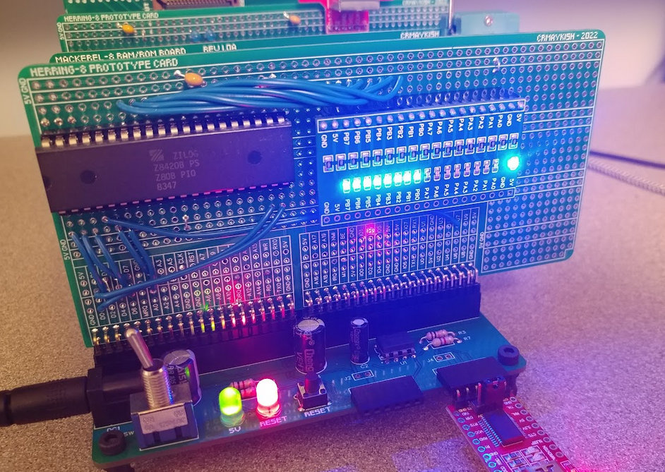
The PIO is a simple chip to program. There are a few different modes for each of the two 8-bit ports, but I just want mode 0 (output) on a single port for now. Once the mode is selected, the output port, hooked up to LEDs in this case, is set by writing to the memory location for port B.
To show signs of life, I incremented port B in a loop, counting up in binary on the LED array:
![]()
It's hard to tell in a photo, but port B is counting up nicely as expected.
The PIO supports a bunch of other features besides being an output port, but I'll save those for another time. We've got blinky lights, the sure sign of a promising hardware project.
-
RC 2022/10 Day 3: Debugging the PS/2 state machine
10/04/2022 at 01:38 • 0 commentsThe PS/2 keyboard interface is one step closer to being useful. I added some code to the monitor program to translate scan codes from the CPLD into ASCII characters for the CPU. This was working for about 20 or 30 characters before the Z180 started reading garbage data from the CPLD.
The Verilog code that handles the PS/2 data in is a state machine that reads once bit at a time and shifts it into a register. Each time the PS/2 clock line goes low, one of these shifts takes place. Each scan code is an 11-bit frame: 1 start bit, 8 data bits, one parity bit, and one stop bit. My suspicion was that the state machine (i.e. the index of the next incoming bit) was being corrupted or otherwise losing sync with the keyboard. The CPLD has no way to know if something like this happens. It will happily keep shifting in bits from the tail end of one scan code and the first half of another. That would certainly cause trouble.
To test this, I added an LED output to the CPLD and set it to turn on at the start of a scan code, i.e. bit 1, and turn off at bit 10 when the scan code read is complete. The PS/2 clock rate is supplied by the keyboard, not the host, but it's generall around 12 kHz. This is definitely slow enough for the LED to act as a nice visual activity indicator for the keyboard.
I was expecting to see the LED flicker when keys were pressed and then turn off. That's what it did for the most part, but when the CPU started reading garbage data, the LED would occasionally stay on, meaning it received a start bit, but no stop bit.
To combat this, I tried to reset the state machine was a bad start or stop bit was detected (start bit is always 0 and stop bit is always 1), but that caused more problems.
After remembering that some of the documentation on the PS/2 mentioned timing and sampling rate being fairly important, I thought maybe the way I was reading in bits was an issue. Long story short: it was. The PS/2 state machine operates in the CPU clock domain. It does not actually treat the PS/2 clock as a clock, just another input. Since the CPU clock is so much faster than the PS/2 clock, the CPLD was reading the PS/2 data line too quickly after the PS/2 clock line was negated and not getting a reliable reading of the actual data line. My solution was to add a delay of 8 CPU cycles after the PS/2 clock goes low before reading the PS/2 data line.
This improved reliability dramatically. It doesn't actually solve any potential issues with the state machine getting out of sync. That's a problem I'll have to deal with eventually, but I think it's a fairly rare occurrence in general.
So I now have crude PS/2 support in the monitor program. It's polling, not interrupt-based, and it's slow. Typing too fast can overload it and characters will be dropped. There is also no support for capital letters or handling shift/control/etc., but it's a start.
** Flounder Z180 System Monitor **
> cpld
PS/2 keyboard test
 this is flounder with a ps2 keyboard
For reference, here's the current Verilog code implementing the PS/2 state machine: https://github.com/crmaykish/flounder-z180/blob/bc3a97c0d7d2850cf11b6a0632c78424655f607b/hardware/flounder_cpld.v
-
RC 2022/10 Day 2: Decoding a PS/2 Keyboard With Verilog
10/03/2022 at 02:51 • 0 commentsI picked up where I left off yesterday by validating the RAM and hooking up one of the Z180's built-in UARTs (called ASCI0 and ASCI1). In both cases I'm just doing the bare minimum to prove out the concept. I've installed a 512KB SRAM chip, but only 16KB is currently mapped into the CPU address space. Eventually, I'd like to understand the MMU and use it address the full range of RAM, but I've got more than enough to keep moving.
Setting up the UART was done in a similarly quick-and-dirty fashion. The Z180 provides some options for deriving serial clocks, and thus baudrates, from the system clock. A common approach is to use an oscillator with a magic frequency like 18.432 MHz and then divide it down within the CPU to get a perfect 9600 or 115,200 baud. My messily-soldered prototypes are not super reliable running at 18 MHz, so my solution was to run the CPU at 1 MHz and provide a second oscillator for the serial clock. Hooking up a 1.8432 MHz to the CKA pin on the Z180 gives a 115,200 baudrate without any additional code setup.
Speaking of serial ports, I modified some portions of the bootloader/monitor I wrote for Herring to run on Flounder so I have a simple serial interface program in C that I can use to quickly test hardware and software changes.
I used this newly functional serial monitor to start work on a PS/2 keyboard interface. One of my main goals for Flounder is that it should be capable of standalone operation. User input is a big part of that. There are lots of interesting I/O methods, key pads, front panel switches, game controllers, but a PS/2 keyboard is simple and ubiquitous.
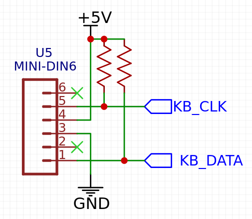
In fact, the PS/2 protocol only requires two pins: CLK and DATA. I wired up the pins to a PS/2 breakout board and to some open I/O pins on the CPLD.
![]()
Both lines also have 4.7k pullups, but these may be redundant. I think most keyboards will already have them.
Since PS/2 is a serial protocol that clocks in scan codes one bit at a time, I'm using the CPLD as a serial-to-parallel converter. The idea is that the CPLD monitors the PS/2 clock line and as it toggles, scan codes are shifted into a register on the CPLD. The Z180 can then address the CPLD like any other memory-mapped peripheral and read the scan code on its 8-bit data bus. The only downside I see to this is that it eats up a lot of CPLD pins: two for the keyboard and eight data bus lines.
I won't cover the details of the PS/2 protocol here. It's available all over the internet and it's pretty straight forward. The only trap I found was assuming that scan codes match ASCII character codes. They don't... I spent a good half hour "debugging" strange values coming in from the keyboard until it dawned on me.
![]()
Fun fact: most USB keyboards are backwards compatible with PS/2 The CPLD is running a simple state machine to decode and parse the PS/2 data. The source as it stands now is available here: https://github.com/crmaykish/flounder-z180/blob/bc4ad37afe275d4681a91163d40dbda921080ad7/hardware/flounder_cpld.v#L38
It's incomplete and not well-tested, but it is at least working. One thought: it seems tempting to use the PS/2 clock line as the clock in the Verilog modules. I think this is a trap. You'll quickly end up having to cross clock domains back to the CPU clock. I just treated the PS/2 clock as another input pin and sampled it from the CPU clock domain.
So I end the day with a proof of concept PS/2 to parallel interface. The next step is to make it a little more practical to use on the software side. I will need to come up with a way to read and acknowledge single key presses instead of constantly outputting the last read scan code. Triggering an interrupt whenever a full scan code is ready and then clearing the interrupt when the CPLD data is read by the CPU is the approach I'm going to attempt.
-
RC 2022/10 Day 1: Soldering...
10/02/2022 at 05:30 • 0 commentsAbout a year ago I collected a few Z180 processors and started doing some research on them. I did the typical new CPU tasks like building a NOP circuit to test the chip, installing and learning some of the software tools and figuring out how to hook up memory. I actually went as far as a having a PCB made up. It worked, but it was a bit of a rush and I abandoed it soon after. All of that to say that I'm not coming at this new Z180 project totally unprepared. Between the proof-of-concept work last year and an additional year of experience with other CPU projects, I feel well prepared to move quickly.
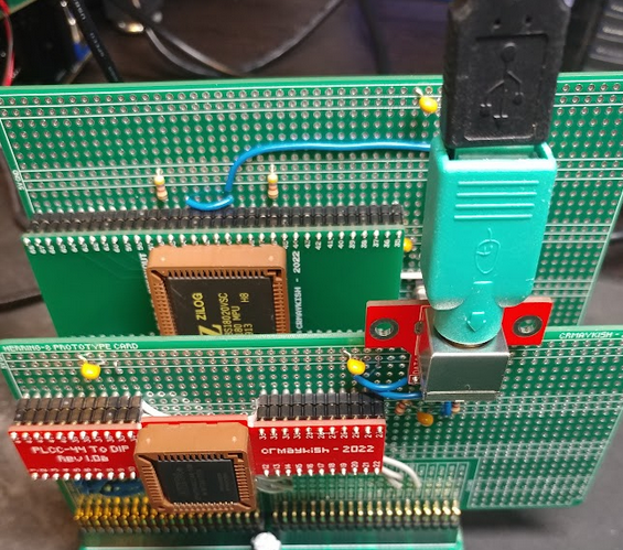
This time around, I decided to forego the NOP circuits or breadboard prototyping and start with hand-soldered boards on the backplane system I've been using on other projects. As I mentioned in the first log, this is not going to be a backplane-based computer, but developing on one for now gives me a lot of flexibility. Today, the first day of the Retro Challenge, was spent building three core boards to get started: CPU, memory, and address decoder on a CPLD.
![]()
After all that soldering, I had minimal time to do much testing, but I wrote up a basic address decoder for the CPLD and recycled some Z180 code from my previous efforts. I checked for the absolute basics like short circuits and missing connections and then fired it up.
One interesting aspect of the Z180 is the ability to run the system clock, PHI, at different multiples of the input oscillator. By default, PHI is set to 1/2 of the oscillator frequency, but it can be set to 1x or 2x as well. One of the first assembly instructions in my code is to set PHI to 1x the oscillator. On the oscilloscope, I was able to verify that with a 2 MHz oscillator, PHI is indeed 1 MHz on boot and then it jumps to 2 MHz. This is as much verification as I had time for today, but it proves that the CPU is alive and that it can execute code from ROM.
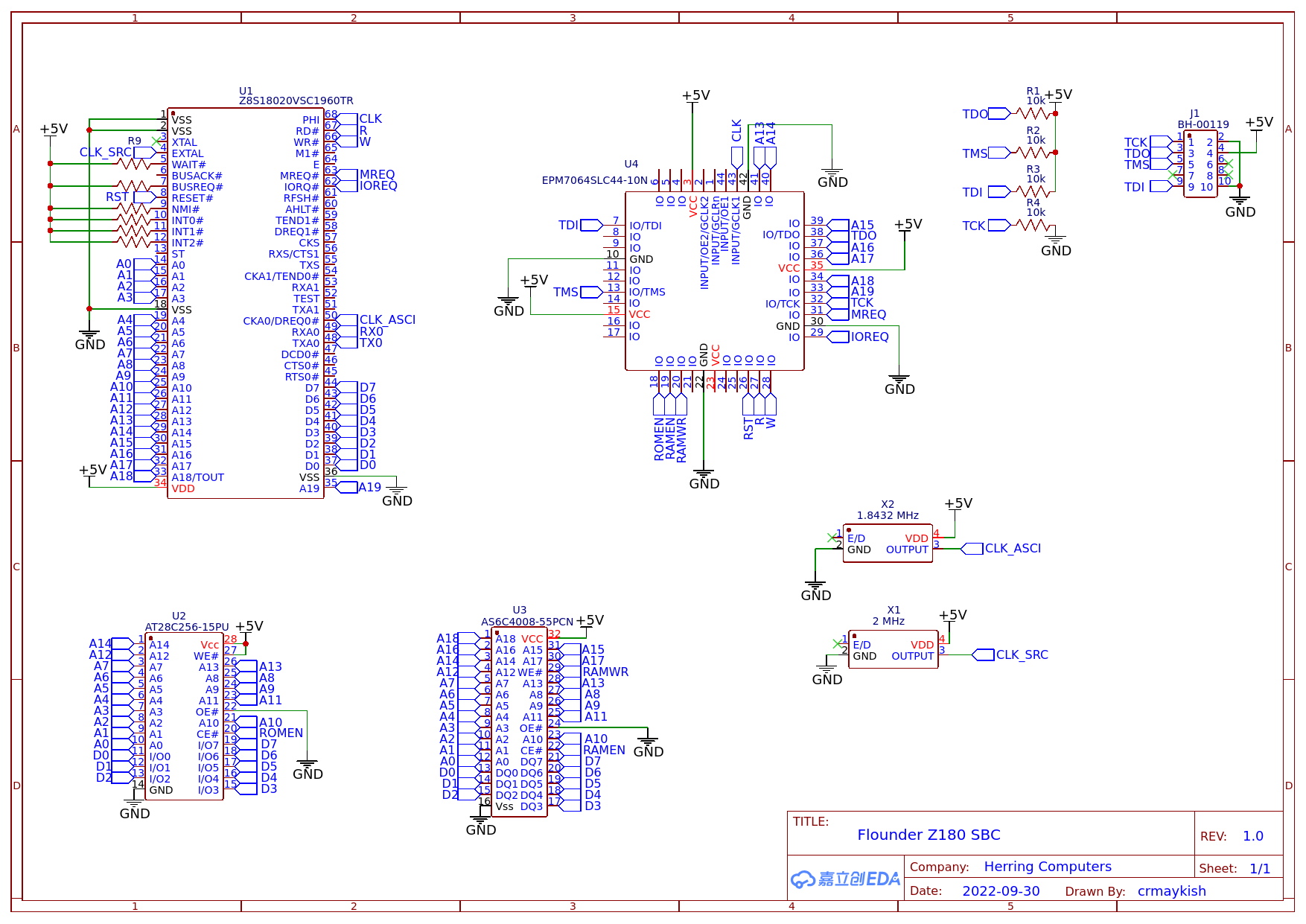
I'm going to try to keep an accurate schematic of this system as I build it in an effort to make PCB design as simple as possible later. Here's what has been wired up so far:
![]()
The next checkpoint will be verifying RAM can be read and written and getting one of the built-in serial ports to work.
-
Mise en place (RC 2022/10)
10/01/2022 at 04:39 • 0 commentsI've been kicking around the idea of building a single-board computer around the Zilog Z180 for a while. It fits nicely between my Herring 6502 and Mackerel 68000 projects. It's got the simplicity of an 8-bit processor with a few more bells and whistles that makes it a little more interesting than the original Z80 for me.
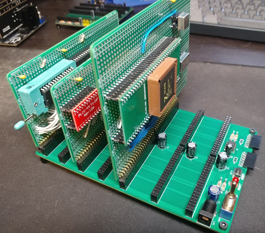
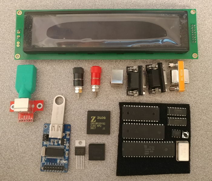
I'm starting this project as my entry into the Retro Challenge 2022/10, https://www.retrochallenge.org/, which runs through the month of October. My goal is to get a functional single-board computer from this pile of parts:
![]()
This collection may evolve over the course of the challenge, but the quick outline is:
- Z180 CPU with 32KB of ROM, 512KB of RAM, and 18.432 MHz oscillator
- USB or banana plugs plus a 5v switching regulator for power
- EPM7064 CPLD for glue logic and possibly some memory-mapped I/O
- MAX232 for 2x RS-232 compatible serial ports (the UARTS are built in to the Z180)
- 555 timer for power-on reset
- PS/2 keyboard connector breakout
- 40x4 LCD display
- CH376S USB-to-parallel interface board
In previous computer projects, I've relied pretty heavily on my PC as the main I/O with the older hardware. This works great, but in the spirit of the Retro Challenge, I'd like to end up with a system that can stand on its own a little better, hence the addition of the nice big LCD display and the PS/2 keyboard. Instead of loading programs over the PC serial port, I'd like to use the CH376 as a "hard drive" allowing the system to operate without a tether.
If I get all of this working within the month, it'll be a miracle, but in the event that I do, my stretch goal is to get a PCB manufactured and build an enclosure. Should be a fun month!
Flounder Z180 Computer
Standalone single-board computer based on the Zilog Z180 CPU