 Peter
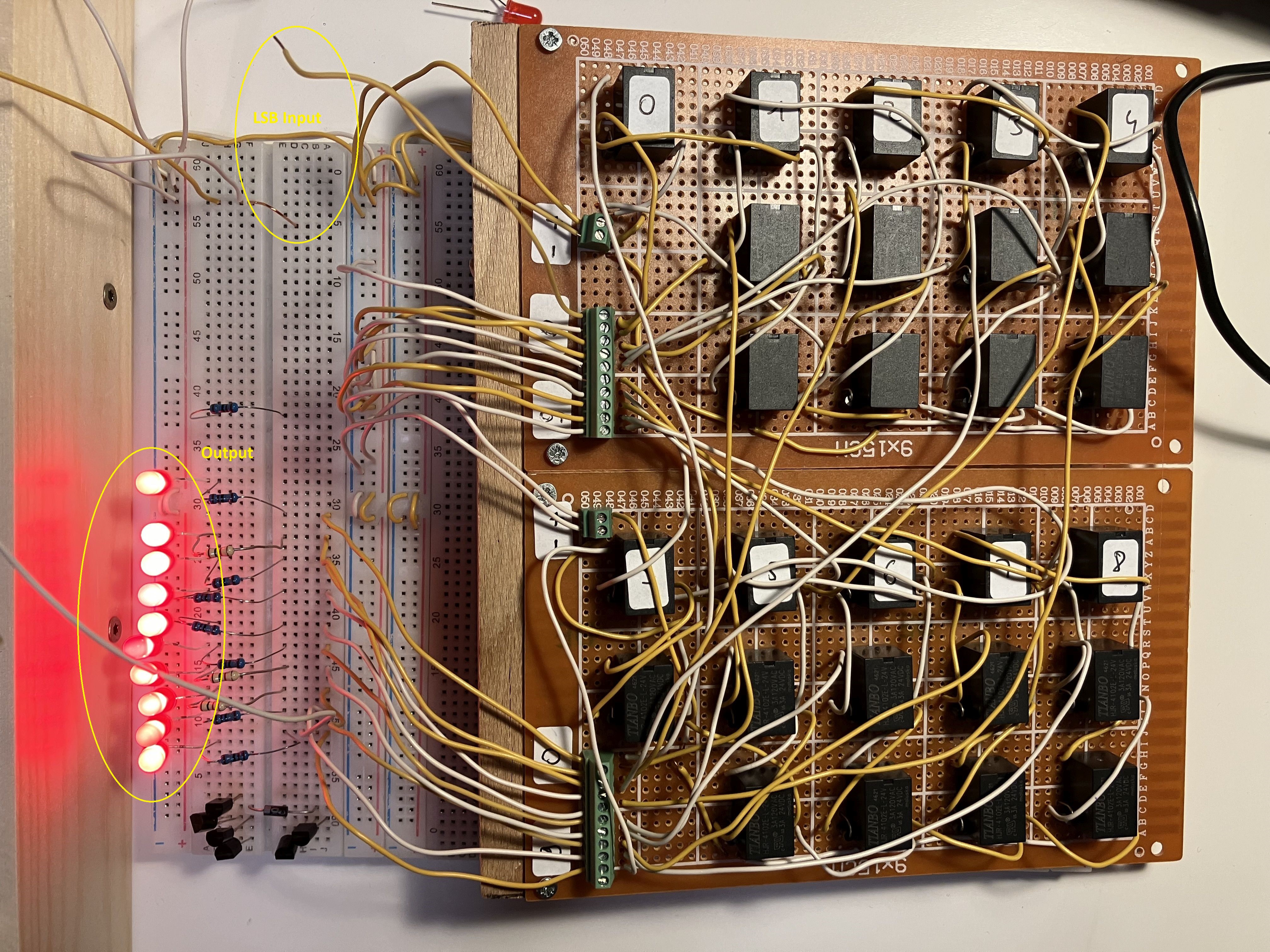
PeterSo, the +1 adder is tested and running. The following picture shows the output of the adder in case of 0xFE as an input, the LSB input (which is not connected) is marked:
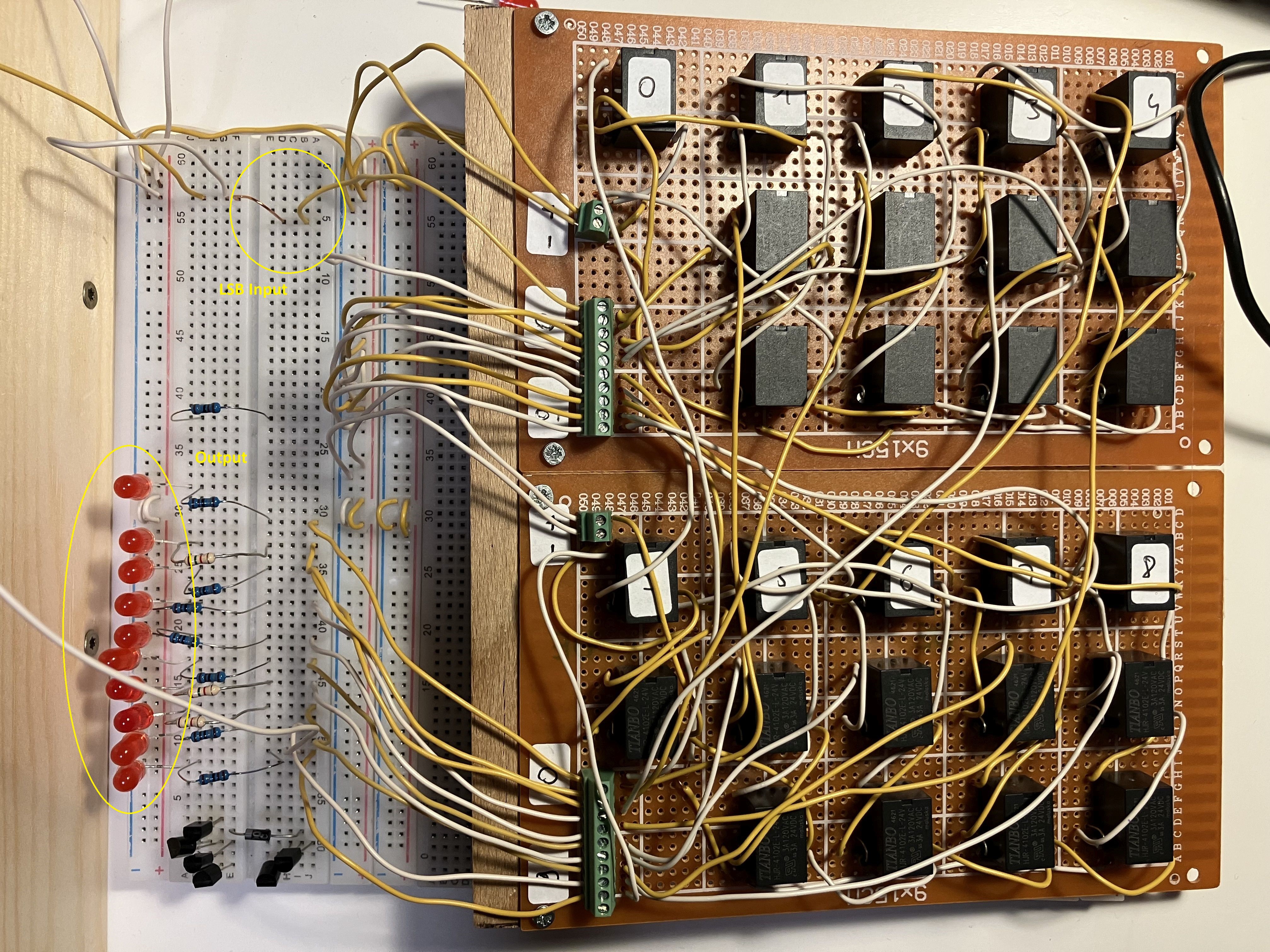
The next piucture shows the output in case of 0xFF as an input...now the LSB input is connected to VCC:
Now I measured the time between the LSB input (from 0 -> 1 and from 1 -> 0) and the MSB output...which is the worst case timing:
The following picture shows the timing if the LSB input switches from 0 - > 1, which means that the counter's output switches from 0xFF to 0x00 (all other inputs are connected to 1):
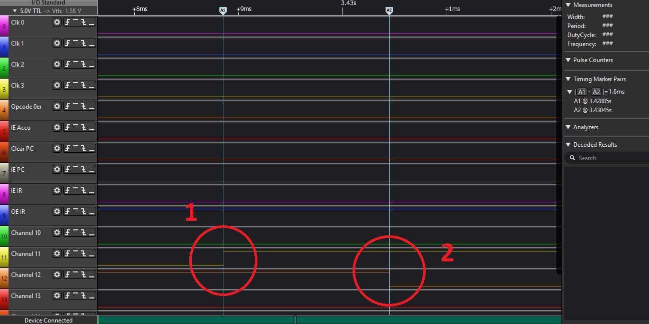
The adder needs only 1,6ms to react, the relays are switched off very fast (1: input signal, 2: output signal).
The following picture shows the timing in case of the LSB input is switching from 1 -> 0, that means the output has to switch from 0x00 to 0xFF:
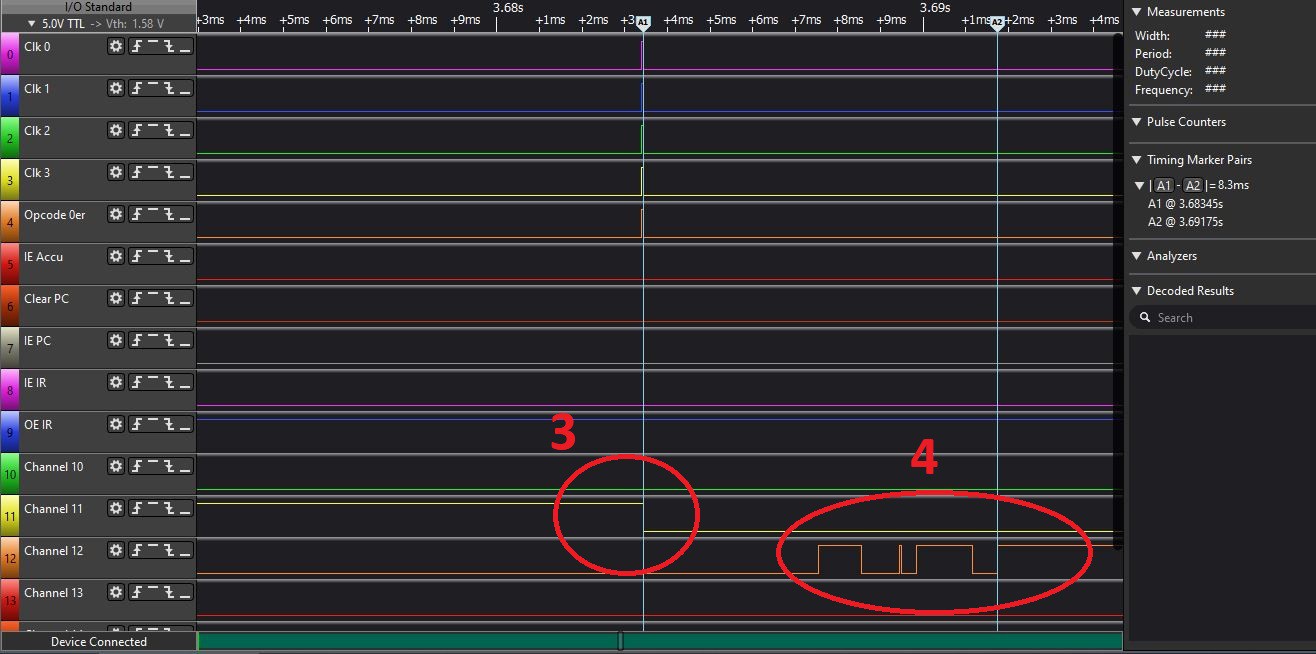
Now the relays has to close the switch, that needs more time and the contacts are bouncing (3: input signal, 4: output signal). Now we have to wait 8,3ms until the output is stable.
That means that 10ms is a secure time to wait until a result is on the adder output if the input is changing.
Discussions
Become a Hackaday.io Member
Create an account to leave a comment. Already have an account? Log In.