 ElectronicABC
GERBER:
https://mega.nz/file/eRwA1Q5D#6HnrcAPaUwlRHEnMkTAI0cX6lRa_7LEuygl4qB_5niA
SCHEMATIC DIAGRAM
HERE WE WILL SEE THE SCHEMATIC DIAGRAM AND ALL THE VALUES OF THE ELECTRONIC COMPONENTS USED FOR OUR TIMER PROJECT.


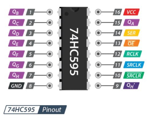
74HC595
INFO
The 74HC595 register allows converting data from serial to parallel format. It is an ideal chip to expand the digital outputs of our Arduino/Pic, 3 Arduino pins can easily handle more than 500 outputs. The 74HC595 is used in the construction of LED Matrix/Cubes, Relay management and more.
The 74HC595 internally has a shift register, a latch register, and tri-state outputs. The shift and storage registers have separate clocks. It has one serial input, eight parallel type outputs (8 bit) and one serial output (Q7S) to use registers in cascade and thus further expand the number of parallel outputs.
TECHNICAL SPECIFICATIONS
Chip: 74HC595
CMOS technology
Compatible with TTL voltages
Operating Voltage: 3.3V - 5V
16 pin DIP type packaging
Offset Frequency (max): 100 MHz
BOOTLOADER ATTINY85
Ok, we have to burn a bootloader to the chi adn then uplaod the code. For both those steps we need the connections below to an Arduino. In my case I will use Arduino UNO. So, make the connections as below between the Arduino SPI port and the PCB. We will sue the Arduino as ISP to uplaod codes.

Install ATtiny Boards
Run your Arduino IDE. We need to install the ATtiny85 boards in case that you don't already have that. To install the boards, copy the link below. Go to Ardduino IDE, to File -> Preferences -> Paste the link in the "Additional Boards Manager URLs". If you already have another link ther, add a comm "," first and then paste the new link. Save and close preferences. Now go to Tools -> Board -> Boards Manager. In this manager search for ATtiny adn install the attiny boards. Now, if you go on tool -> board, you should see the ATtiny boards as well.

Arduino As ISP
In order to use the Arduino as an ISP programmer, we need to uplaod a code to it so for taht, go to Examples -> ArduinoISP -> ArduinoISP and open that example code. Then make sure yous elect the type of board for your Arduino, in my case, Arduino UNO. Select the com and leave the default programmer as "AVRISP mkII". Connect the USB, select the COM and uplaod the code to the Arduino UNO.

Bootloader Burn
Ok, now the Arduino has the ISP code so it will act as a ISP programmer. Now, let's butn the bootloader. Go to Tools -> Board and selectt the ATtiny25/45/85 type of board. Then, once that is selected, go to Tools -> Processor -> And select the ATtiny85. Then go to Clock -> and select the internal 8MHz one so we will burn that bootlaoder. Go to Tools -> Programmer and make sure you now change the normal programmer from "AVRISP mkII" to "Arduino as ISP". Finally, amke sure the Arduino UNO is connected to the PCB to the ISP port and go to Tools -> Burn Bootloader. The Arduino Rx/Tx LEDs will blink and after a while you will get the bootloader burn complete on the screen.


CODE ARDUINO


int clockpin = 2; //Cuando ay que leer los bit      SH
    int data     = 1;   //Envio datos                     DS
    int latch    = 0;  //indica pin de salida en el chip ST


    // no cambiar el const int
    const int  left_sen  = 4 ;   // pin 2 como entrada para el sensor izquierdo
    const int  right_sen = 3;    // pin 3 como entrada para el sensor derecho


    //VARIABLES PARA EL CONTADOR ASCENDIENTE
    // estas variables si puede ser cambiado
    int contador             = 0;
    int contadorU            = 0;
    int contadorD            = 0;
    int contadorC            = 0;
    int contadorM            = 0;
    int estado_left_sen      = 0;      // estado  del pulsado actual
    int lastButtonState_left = 1;     // estado  del pulsado anterior


    boolean start            = false;
    boolean start1           = false;
    boolean ena_D            = false;
    boolean ena_C            = false;
    boolean ok               = false;


    unsigned long time;
    float tiempo = 1000;
    unsigned long  t = 0;


    //VARIABLES PARA EL CONTADOR DESCENDIENTE
    // estas variables si puede ser cambiado


    int estado_right_sen      = 0;         // estado  del pulsado actual
    int lastButtonState_right = 1;     // estado  del pulsado anterior


    //Aqui esta el array que contiene todos los UNDs para nuestro display
    //El display tiene las conexiones alcontrario ell pin 8 del 74hc595 es el primer dijito binario


    const int NUM[] = { // segmentos
      191,   //Numero 0 en binario es : 10111111
      134,   //Numero 1 en binario es : 10000110
      219,   //Numero 2 en binario es : 11011011
      207,   //Numero 3 en binario es : 11001111
      230,   //Numero 4 en binario es : 11100110
      237,   //Numero 5 en binario es : 11101101
      253,   //Numero 6 en binario es : 11111101
      135,   //Numero 7 en binario es : 10000111
      255,   //Numero 8 en binario es : 11111111
      239,   //Numero 9 en binario es : 11101111
      191,   //Numero 0 en binario es : 10111111


      14,    //Numero 7 en binario es : 00001110
      13,    //Numero 8 en binario es : 00001101
      11,    //Numero 9 en binario es : 00001011
      7,     //Numero 0 en binario es : 00000111


      46,    //Numero 7 en binario es : 00101110
      45,    //Numero 8 en binario es : 00101101
      43,    //Numero 9 en binario es : 00101011
      39,    //Numero 0 en binario es : 00100111


    };


    void setup() {


      pinMode(left_sen, INPUT);
      pinMode(right_sen, INPUT);


      pinMode(latch, OUTPUT);
      pinMode(clockpin, OUTPUT);
      pinMode(data, OUTPUT);


    }
    void loop()
    {
      if (start == false) {
        digitalWrite(latch, LOW);
        shiftOut(data, clockpin, MSBFIRST, NUM[11]); // lee el arreglo y pasa cada NUM a lectura binaria
        shiftOut(data, clockpin, MSBFIRST, NUM[0]); // lee el arreglo y pasa cada NUM a lectura binaria
        digitalWrite(latch, HIGH);
        delayMicroseconds(1);
        digitalWrite(latch, LOW);
        shiftOut(data, clockpin, MSBFIRST, NUM[12]); // lee el arreglo y pasa cada NUM a lectura binaria
        shiftOut(data, clockpin, MSBFIRST, NUM[0]); // lee el arreglo y pasa cada NUM a lectura binaria
        digitalWrite(latch, HIGH);
        delayMicroseconds(1);


        digitalWrite(latch, LOW);
        shiftOut(data, clockpin, MSBFIRST, NUM[13]); // lee el arreglo y pasa cada NUM a lectura binaria
        shiftOut(data, clockpin, MSBFIRST, NUM[0]); // lee el arreglo y pasa cada NUM a lectura binaria
        digitalWrite(latch, HIGH);
        delayMicroseconds(1);


        digitalWrite(latch, LOW);
        shiftOut(data, clockpin, MSBFIRST, NUM[14]); // lee el arreglo y pasa cada NUM a lectura binaria
        shiftOut(data, clockpin, MSBFIRST, NUM[0]); // lee el arreglo y pasa cada NUM a lectura binaria
        digitalWrite(latch, HIGH);
        delayMicroseconds(1);
      }


      estado_left_sen = digitalRead(left_sen);
      estado_right_sen = digitalRead(right_sen);


      if (estado_left_sen != lastButtonState_left) {
        if (estado_left_sen == HIGH) {
          start = true;
          start1 = false;
          ok = false;


          if (contador <= 5940) {


            if (contadorU >= 10) {
              contadorU = 0;
            }
            if (contadorU >= 9) {
              contadorD++;
            }
            if (contadorD >= 6) {
              contadorD = 0;
              contadorC++;
            }
            if (contadorC >= 10) {
              contadorC = 0;
              contadorM++;
            }
            if (contadorM >= 6) {
              contadorM = 0;
            }
            contador++;
            contadorU++;


          }


        }
      }
      lastButtonState_left  = estado_left_sen;


      if (estado_right_sen != lastButtonState_right ) {
        if (estado_right_sen == HIGH) {
          start1 = true;
          //start = false;
          ok = true;
        }
      }
      lastButtonState_right  = estado_right_sen;


      if (start1 == true) {
        time = millis();
        if (time - t > tiempo) {
          t = time;
          if (contador > 0) {
            contador--;
            contadorU--;


            if (contadorU == 0) {


              contadorU = 10;


            }


            if (contadorU == 9) {
              if (contadorD > 0) {
                contadorD--;
              }
            }
            else if (contadorD == 0 && contadorU == 10) {
              ena_D = true;
            }


            if ((ena_D == true) && (contadorU == 9)) {


              if (contadorC > 0) {
                contadorD = 5;
                ena_D = false;
                contadorC--;
              }
            }
            if (contadorC == 0 && contadorD == 0 && contadorU == 10) {
              ena_C = true;
            }
            if (ena_C == true && contadorD == 5 && contadorU == 9) {
              if (contadorM > 0) {
                contadorC = 9 ;
                ena_C = false;
                contadorM--;
              }


            }
          }
        }
        cont ();
      }
      if (contadorU == 10 && contadorD == 0 && contadorC == 0 && contadorM == 0) {
        ok = false;
      }
      if (start == true) {
        cont ();
      }


    }
    void cont() {
      digitalWrite(latch, LOW);
      if (ok == false && contadorU >= 0 && contadorD >= 0 && contadorC >= 0 && contadorM >= 0) {
        shiftOut(data, clockpin, MSBFIRST, NUM[11]); // lee el arreglo y pasa cada NUM a lectura binaria
      }
      else if (ok == true && (contadorU > 0 || contadorD > 0 || contadorC > 0 || contadorM > 0)) {
        shiftOut(data, clockpin, MSBFIRST, NUM[15]); // lee el arreglo y pasa cada NUM a lectura binaria
      }
      shiftOut(data, clockpin, MSBFIRST, NUM[contadorM]); // lee el arreglo y pasa cada NUM a lectura binaria
      digitalWrite(latch, HIGH);
      delayMicroseconds(1);


      digitalWrite(latch, LOW);
      if (ok == false && contadorU >= 0 && contadorD >= 0 && contadorC >= 0 && contadorM >= 0) {
        shiftOut(data, clockpin, MSBFIRST, NUM[12]); // lee el arreglo y pasa cada NUM a lectura binaria
      }
      else if (ok == true && (contadorU > 0 || contadorD > 0 || contadorC > 0 || contadorM > 0)) {
        shiftOut(data, clockpin, MSBFIRST, NUM[16]); // lee el arreglo y pasa cada NUM a lectura binaria
      }
      shiftOut(data, clockpin, MSBFIRST, NUM[contadorC]); // lee el arreglo y pasa cada NUM a lectura binaria
      digitalWrite(latch, HIGH);
      delayMicroseconds(1);


      digitalWrite(latch, LOW);
      if (ok == false && contadorU >= 0 && contadorD >= 0 && contadorC >= 0 && contadorM >= 0) {
        shiftOut(data, clockpin, MSBFIRST, NUM[13]); // lee el arreglo y pasa cada NUM a lectura binaria
      }
      else if (ok == true && (contadorU > 0 || contadorD > 0 || contadorC > 0 || contadorM > 0)) {
        shiftOut(data, clockpin, MSBFIRST, NUM[17]); // lee el arreglo y pasa cada NUM a lectura binaria
      }
      shiftOut(data, clockpin, MSBFIRST, NUM[contadorD]); // lee el arreglo y pasa cada NUM a lectura binaria
      digitalWrite(latch, HIGH);
      delayMicroseconds(1);


      digitalWrite(latch, LOW);
      if (ok == false && contadorU >= 0 && contadorD >= 0 && contadorC >= 0 && contadorM >= 0) {
        shiftOut(data, clockpin, MSBFIRST, NUM[14]); // lee el arreglo y pasa cada NUM a lectura binaria
      }
      else if (ok == true && (contadorU > 0 || contadorD > 0 || contadorC > 0 || contadorM > 0)) {
        shiftOut(data, clockpin, MSBFIRST, NUM[18]); // lee el arreglo y pasa cada NUM a lectura binaria
      }
      shiftOut(data, clockpin, MSBFIRST, NUM[contadorU]); // lee el arreglo y pasa cada NUM a lectura binaria
      digitalWrite(latch, HIGH);
      delayMicroseconds(1);
    }
ELECTRONIC COMPONENTS
- 2 DIODOS 1N5819 SMD
- 3 CAP. 100NF 1206
- 2 BT3904 TRANSISTOR NPN SMD
- 3 RESISTOR 1K 1206 SMD
- 4 RESISTOR 10K 1206 SMD
- 8 RESISTOR 220 ohm 1206 SMD
- 1 DIODO 1N4148 SMD
- 1 DIODO LED 1206 RED
- 3 BUTTON 4 PINS
- 4 DISPLAY CATODO COMUN
- 1 BUZZER 5VDC
- 2 CI 74HC595
- 1 RELE 5VDC
- 1 TERMINAL BLUE 2 PIN
- 1 TERMINAL BLUE 3 PIN
- 1 PCB
EASYEDA
Once the project is finished with all the respective tests, we carry out the PCB design and we will obtain the routed tracks and the 3D image of how our finished PCB would look.


JLCPCB
Once the pcb is designed, we will send our friends from JLCPCB to manufacture our PCB.
5pcbs only $2
JLCPCB number 1 PCB manufacturing company worldwide professional pcbs and excellent finish.
GERBER PCB:
https://mega.nz/file/eRwA1Q5D#6HnrcAPaUwlRHEnMkTAI0cX6lRa_7LEuygl4qB_5niA

