 Burkhard Kainka
The circuit
Functional description
The function is triggered either by a light pulse on the yellow LED (as a photodiode), by touching the input or by an electromagnetic pulse. After that, there is a pause of about half a second. And then there is a sound, which at first reminded me of the unwilling meowing of a cat, which does not want to be disturbed. One understands it intuitively, the cat says: "Leave me alone, I want to sleep!"
We make similar noises when we feel disturbed. Everyone knows the situation. You are sitting concentrated at work and someone comes in, the flow of work and concentration are disturbed. At first, you don't want to be rude and you stay quiet for a moment. But then the internal pressure increases and you say "Oh!", or "No!" or even "Crap!". No matter what you say, it always has the same reproachful sound with descending frequency at the end. And everyone understands that there's more to it than just a word, namely, "I want to do creative work here, and you just come in and bother me! Don't you have anything to do? Just get out again!" Everyone understands, except that one colleague who sees his job as keeping others from working because he himself never works properly.
If you now try to reproduce this behavior in the circuit diagram, you may have some difficulties. If now all say, this can never work, my goal is reached. I wanted to build a circuit that is difficult to understand. And at the same time it should perform a complex function with as few components as possible.
Trigger circuit
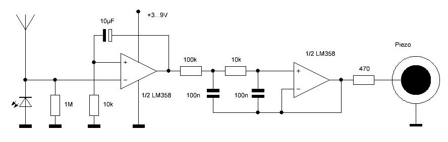
The first part of the circuit is a very sensitive triggered monostable flipflop with an additional slow falling back edge. I came across the principle by accident when working with an LM358. With a LM324 it works as well. It is essential that this op amp has a PNP input stage, with which the inputs work down to the GND level and even a bit below. These types were developed for use with single operating voltages from 3 V.
The two inputs have a base current of approx. 20 nA. An open input would be pulled up. So I can generate a bias voltage via the voltage drop at a resistor to GND, similar to what was done at some old tube circuits. At the -input I use 1 MΩ, so there is a voltage of + 20 mV here. In a separate experiment you can also use 220 kΩ to make the circuit even more sensitive. The +input gets only 10 kΩ and therefore has only 0.2 mV, so it is almost at GND. As the -input is clearly higher than the +input the output stays at the bottom. However, a very small negative voltage spike of about 20 mV is enough to drive the output high. In that case, the capacitor charges up and pulls the +input high. This keeps the output high for a longer time, just like a normal monoflop. By the way, the time is much longer than the time constant 10 µF * 10 kΩ = 10 ms, because the voltage has to drop below 20 mV to end the pulse.
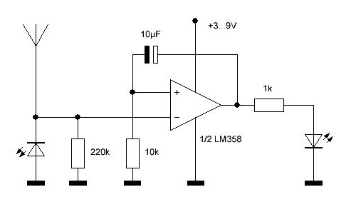
If an LED is connected to the output, it turns on for about half a second with each trigger event. Triggering is done e.g. with a light pulse to the left LED, which acts as a photodiode. A yellow LED has proven itself well here. With full light it can generate a voltage of more than 1.5 V. The cathode is at the input here, so a negative voltage is output. In fact, it only needs to deliver a little more than 20 nA to compensate for the input current of the OPV. It easily manages this with the light beam of an LED flashlight, which briefly wanders over the sensor LED.
A wire antenna is as well connected to the input. If one touches the bare wire, usually some interference voltage is coupled in. A few millivolts are enough to trigger the circuit. The same thing happens with an electromagnetic pulse when you flip a light switch, for example. Or you can use a piezo lighter at a distance of 10 cm. The electric spark will generate the necessary pulse. A simple lighter with a flint also works because the bright flash of light is detected by the sensor LED. Up to here this is a normal monoflop. Only the PNP input stage is important. It wouldn't work with an LM741 because it uses NPN transistors at the input, which pull down the inputs. And a modern rail-to-rail CMOS amp wouldn't work either because it has no input current. It has to be one of those good old LM358 or LM324.

But now comes another special feature. The falling slope is not steep, but inclined. You can see a slowed down linear descent of the voltage. To be more precise, it starts with a steep descent that only changes to the slowed down descent after a drop of 0.5 V. Something happens here that is explicitly forbidden in the data sheets, but does not destroy the IC. The voltage at the +input drops about 0.5 V below zero, but allowed is -0.3 V at most. When you reach approx. -0.5 V the function of the input reverses! The +input becomes an inverting input, the feedback becomes a negative feedback. Thus the capacitor becomes part of an integrator, which provides for the linear descent of the output voltage.
The Philbrick Oscillator
The oscillator is also in need of explanation. For closer examination I built it separately with slightly different parts. This time a CMOS-OPV MCP602 was used, which is closer to an ideal op amp. At first glance, you can actually only see a low-pass filter because the amplifier operates with full negative feedback and voltage gain 1.

In fact this is a Philbrick oscillator working with stacked high pass filters. For clarification I have simulated the RC network individually with LTspice. In this you can see that there is a frequency range where the passive network has a gain > 1. The phase shift is getting closer and closer to 0. One can see that the oscillation condition is thus fulfilled. So the oscillator oscillates although the amplifier does not amplify. A particularly large voltage boost is obtained when a high-impedance high-pass filter is added to a low-impedance high-pass filter, as was done here.

Actually I had expected a sinusoidal signal. But the oscillator is already driven so far that the signal is clipped. In the test circuit there is a potentiometer, with which I can preset the middle voltage. At the very edges the signal gets smaller. At a medium voltage you get the largest amplitude with a symmetrical signal.

Input voltage almost 5 V

Input voltage near 2.5 V

Input voltage almost 0 V
The measurements also show that the frequency becomes significantly smaller at the upper and lower ends of the input voltage. This is the reason for the falling pitch of the audio signal. I must confess, this surprised me. Actually, I had expected a sinusoidal signal that only changes its amplitude. But what came out in the end is even more complex than I thought.
Circuit details
Again back to the final circuit. Here the impedances in the Philbrick oscillator were dimensioned differently. The main reason was to avoid a reaction of the oscillator to the monoflop. Therefore the first resistor with 100 kΩ is chosen very large, the second much smaller. In addition, two equal capacitors were used. The voltage rise turns out much smaller with it, but is still sufficient for a safe oscillation. With swapped resistors I had the problem that the oscillator could always retrigger the first stage. This is eliminated with the final dimensioning.

If you listen closely, there is a faint sound right at the beginning of the monoflop pulse. It occurs because the circuit is actually more of a low-pass filter when viewed from the first stage. So it takes a short moment for the average DC voltage to rise enough for the oscillator to stop working altogether. At the end of the monoflop pulse, the voltage drops abruptly by 0.5 V. The oscillator thus immediately enters a range of high volume and medium frequency. So the frequency change becomes perceptible mainly at the end. This creates the characteristic sound of a heavily annoyed exclamation.

The sound with several harminics in SDR#
The antenna is only about 10 cm long. However, you can extend it on a trial basis and also change the position of the device. If the antenna becomes too long, the noise can already be triggered by the alternating fields of the power lines that are always present in closed rooms. But if you find the right length and place the antenna close to the door, it will already react to people entering with their static electric fields surrounding them. At some point, everyone may have understood that one would like to work undisturbed.