Ratti3
Video of project:
The features and functions of this device are:
- Adjustable charge voltage and current with a battery store mode
- Adjustable boost voltage and current
- SSD1306 OLED display
- Rotary encoder for menu selection
- Low battery charge mode
- Reverse battery polarity protection using MOSFETs
- 3 AMP Fast Charge current and 2 AMP powerbank output
- USB C, Type A and Micro ports
- NTC thermistors for the battery and IC temperature monitoring
- ICSP header
- Buzzer for audio feedback
- Low power mode and full auto power off mode
- Heatsink to dissipate the 3 AMP of charging switching loss
- WS2812B indicator LEDs
A lot of the features are autonomous and if desired can be changed via the code. The BQ25896 is controllable and configurable via I2C, and has 15 Register Maps and the driver library has references to all of them.
The image below shows the simplified schematic of a charger circuit, this particular version of the IC the VBUS and OTG out share the same pin. The driver library can be adapted to use with other BQ2589x ICs.
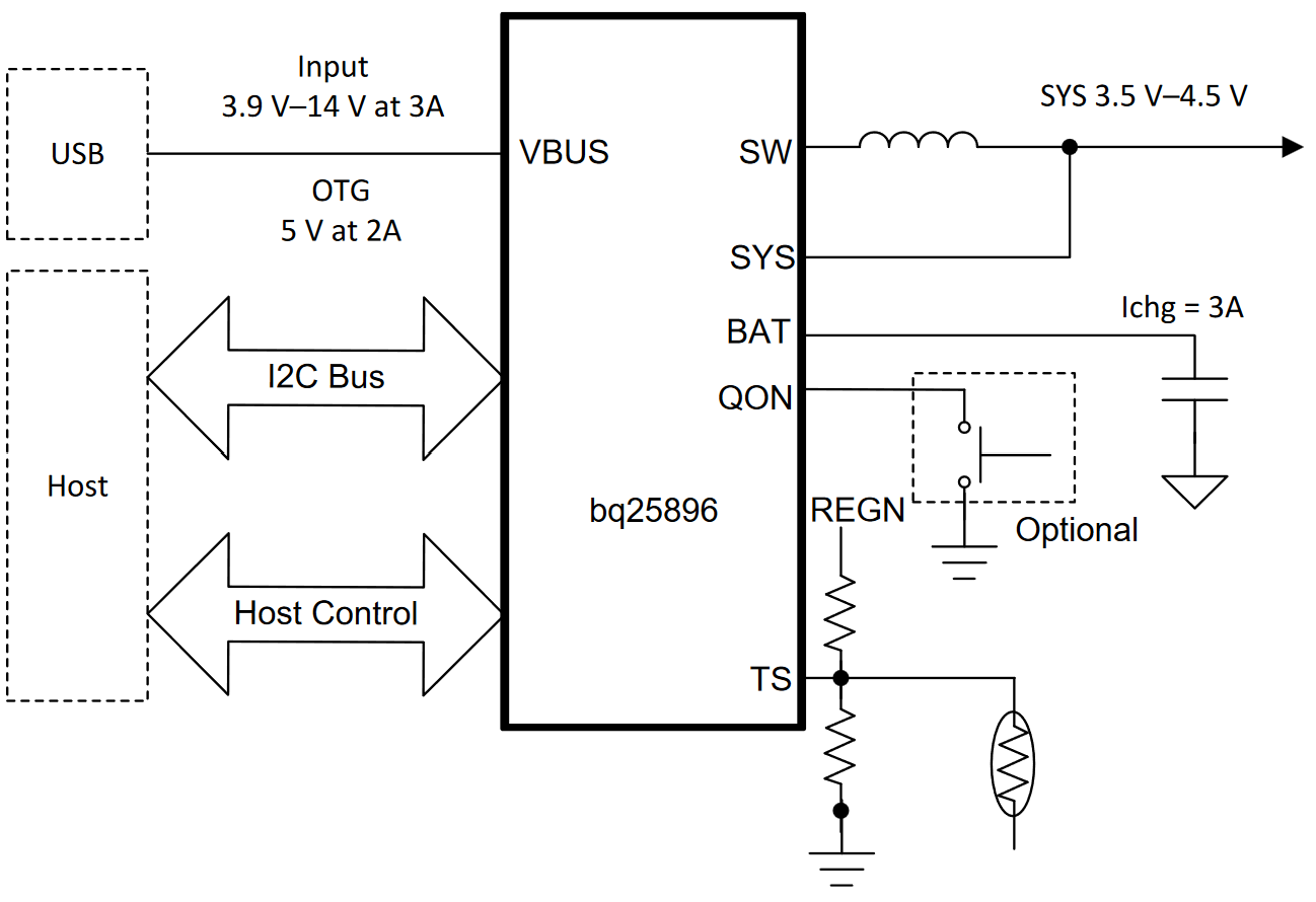
According to the Texas Instruments datasheet these are features of the IC:
- 92.5% Charge Efficiency at 2 A and 90.5% Charge Efficiency at 3 A Charge Current
- USB On-the-Go (OTG) with Adjustable Output from 4.5 V to 5.5 V with up-to 2 A Output
- 93% Boost Efficiency at 5 V at 1 A Output
- Support down-to 2.5V Battery
- Integrated ADC for System Monitor (Voltage, Temperature, Charge Current)
- ±0.5% Charge Voltage Regulation, ±5% Charge Current Regulation, ±7.5% Input Current Regulation
An Atmel ATMEGA32U4 MCU is used to send commands to the BQ25896, during bootup a sequence commands are sent to set the IC to a baseline. After that the rotary encoder can be used to change some of the settings. All settings are saved to EEPROM. As there is only 28KB of usable flash I was unable to make fancy battery level indicators, in hindsight I should have used an ATSAMD21.
The voltage for the ATMEGA32U4 and the OLED is supplied via BAT/SYS, when there is a USB input VSYS is maintained at VSYS_MIN (3.6V). When running on battery it tracks the battery voltage, so it does mean VSYS can drop to as low as 2.9V, as the MCU and OLED are fed via the 3.3V LDO the voltages can drop very low.
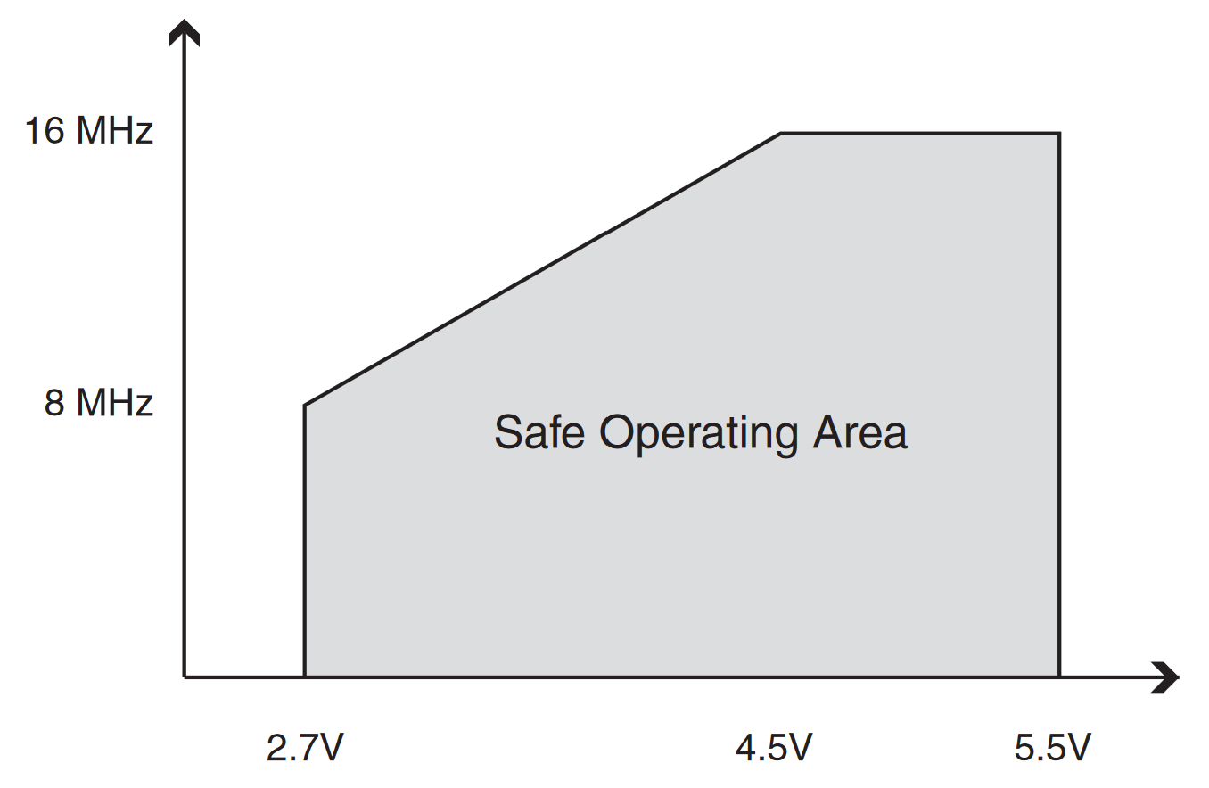
The safe operating area for the ATMEGA32U4 is as low as 2.7V when running at 8MHz. The SSD1306 OLED voltage range is 1.65 - 3.3V.
I have tested this and seems to operate ok at these low voltages, but there were a couple of times when the battery dropped below 3.1V and when in BOOST mode with 2A being drawn the MCU malfunctioned.
Arduino IDE .INO File
The .INO file can be found in the Release folder of the Github repository, the code has a lot of comments. I used Zadig to load a driver and then used the ICSP header to load the SparkFun Pro Micro bootloader. After that the device is recognised via the MicroUSB port on Windows10/11.
After compiling the sketch uses the following program space:
Sketch uses 28536 bytes (99%) of program storage space. Maximum is 28672 bytes.
Global variables use 1105 bytes (43%) of dynamic memory, leaving 1455 bytes for local variables. Maximum is 2560 bytes.
The following libraries used, the Adafruit SSD1306 library needs to be edited to remove the splash screen, mask out #include "splash.h" in file Adafruit_SSD1306.cpp, otherwise it does not fit the ATMEGA32U4.
#include <Wire.h>
#include <EEPROM.h>            // v2.0    | https://github.com/PaulStoffregen/EEPROM
#include <BQ2589x.h>           // v1.0    | https://github.com/Ratti3/BQ2589x
#include <FastLED.h>           // v3.5.0  | https://github.com/FastLED/FastLED
#include <TimerOne.h>          // v1.1.1  | https://github.com/PaulStoffregen/TimerOne
#include <LowPower.h>          // v2.2    | https://github.com/LowPowerLab/LowPower
#include <AbleButtons.h>       // v0.3.0  | https://github.com/jsware/able-buttons
#include <BasicEncoder.h>      // v1.1.4  | https://github.com/micromouseonline/BasicEncoder
#include <Adafruit_GFX.h>      // v1.11.5 | https://github.com/adafruit/Adafruit-GFX-Library
#include <Adafruit_SSD1306.h>  // v2.5.7  | https://github.com/adafruit/Adafruit_SSD1306 (this needs to be modified to remove the splash screen otherwise it will not fit the ATMEGA32U4 flash)
These are some of the default values that can be changed, note any values cannot be used, the decimal numbers must correlate with the Registry Map values. Check the TI PDF or my notes in the driver library.
#define STOREVOLTAGE 3750                                // VCHG Voltage for storage
int arrVCHG[4] = { 3840, 4096, 4192, 4208 };             // Charge voltage values (first one is used to set the STOREVOLTAGE, it is the minimum allowed value)
byte arrPositionVCHG = 2;                                // Set default charge voltage to 4.192V
int arrICHG[6] = { 512, 1024, 1536, 2048, 2560, 3072 };  // Charge current values
byte arrPositionICHG = 5;                                // Set default charge current to 3A
int arrVOTG[3] = { 4998, 5062, 5126 };                   // Boost voltage values
byte arrPositionVOTG = 1;                                // Set default boost voltage to 5.062V
int arrIOTG[5] = { 500, 750, 1200, 1650, 2150 };         // Boost current values
byte arrPositionIOTG = 4;                                // Set default boost current to 2.15A
byte oledRotation = 2;                                   // OLED default rotation setting
int arraySleep[3] = { 60, 120, 300 };                    // Sleep/Ship Mode timeout values in seconds
byte arrPositionSleep = 0;                               // Default Sleep/Ship Mode value
int arrayLED[4] = { 5, 10, 15, 20 };                     // LED brightness values
byte arrPositionLED = 0;                                 // Default LED brightness
BQ25896 Driver Library
The driver library can be found in the Github repository and has a lot of comments. There should not be a need to edit this. Here is what one of the Register Maps look like:
/* Register 0x04 *********************************************************************************************
    7     6     5     4     3     2     1     0 : BIT
    0     0     1     0     0     0     0     0 : Chip Default
    0     0     1     0     0     0     0     0 : Code Default
   R/W   R/W   R/W   R/W   R/W   R/W   R/W   R/W
   Bit   Field       Type   Reset               Description
    7    EN_PUMPX    R/W    REG_RST/Watchdog    Current pulse control Enable
                                                 0 - Disable Current pulse control (default)
                                                 1 - Enable Current pulse control (PUMPX_UP and PUMPX_DN)
    6    ICHG[6]     R/W    REG_RST/Watchdog    4096mA   Fast Charge Current Limit
    5    ICHG[5]     R/W    REG_RST/Watchdog    2048mA   Offset: 0mA
    4    ICHG[4]     R/W    REG_RST/Watchdog    1024mA   Range: 0mA (0000000) – 3008mA (0101111)
    3    ICHG[3]     R/W    REG_RST/Watchdog    512mA    Default: 2048mA (0100000)
    2    ICHG[2]     R/W    REG_RST/Watchdog    256mA    Note: ICHG=000000 (0mA) disables charge
    1    ICHG[1]     R/W    REG_RST/Watchdog    128mA    ICHG > 0101111 (3008mA) is clamped to register value 0101111 (3008mA)
    0    ICHG[0]     R/W    REG_RST/Watchdog    64mA
*/
#define BQ2589X_REG_04         0x04
#define BQ2589X_EN_PUMPX_MASK  0x80 // BIT 7   10000000
#define BQ2589X_EN_PUMPX_SHIFT 7
#define BQ2589X_PUMPX_ENABLE   1
#define BQ2589X_PUMPX_DISABLE  0    // Default
#define BQ2589X_ICHG_MASK      0x7F // BIT 0-6 01111111
#define BQ2589X_ICHG_SHIFT     0
#define BQ2589X_ICHG_BASE      0
#define BQ2589X_ICHG_LSB       64   // 64mA
Schematics, Gerbers and Pick & Place Files
The most up to date schematics, BOM and PCBs can be found here:
https://oshwlab.com/ratti3/bq25896-lithium-battery-charger-with-oled-display
https://oshwlab.com/ratti3/ssd1306-0-96-i2c-oled-display
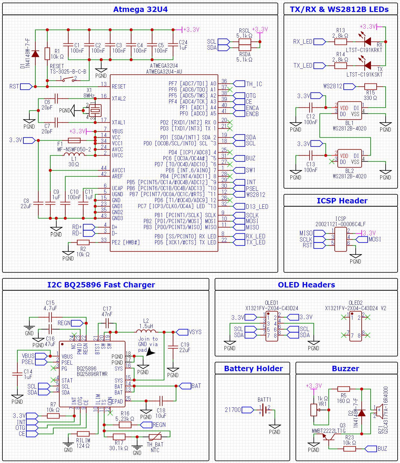
Here is part of the schematic, the BQ25896 is based on the TI reference design, the ATMEGA32U4 is based on the Arduino Micro reference design with minor changes.
To keep power consumption low the ATMEGA32U4 is configured for 8MHz and 3.3V.
Gerbers and Pick & Place files can be generated using EasyEDA or the ones I used can be found in the Github repository.
https://github.com/Ratti3/BQ2589x-ATMEGA32U4-Charger-Powerbank-with-SSD1306-OLED
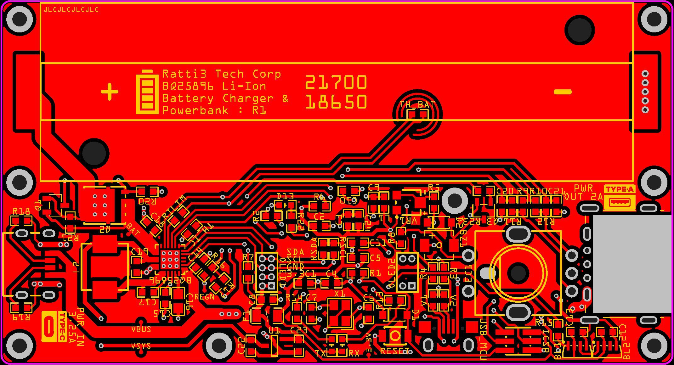
Here is what the main PCB looks like on EasyEDA:
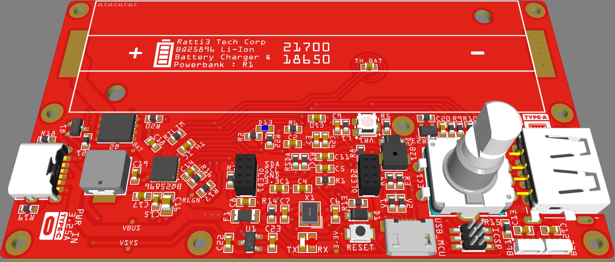
3D model of the main PCB:
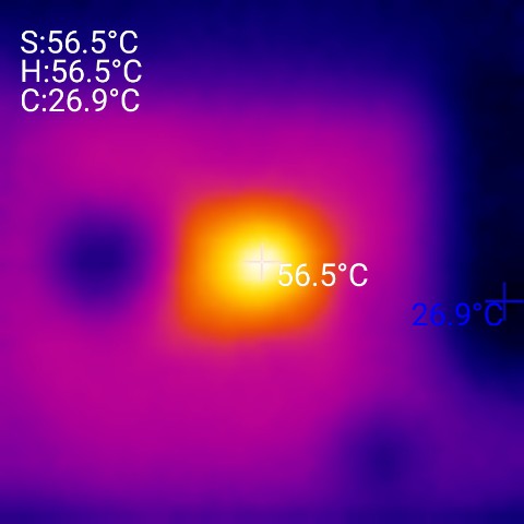
Thermal Measurements
I used a thermal camera to take some readings when charging at 2.85A @ 4V vBAT, as you can see the BQ25896 reaches a peak temperature of 56 degrees with an ambient temperature of 20 degrees:
The temperature of the heatsink was 40.9 degrees:

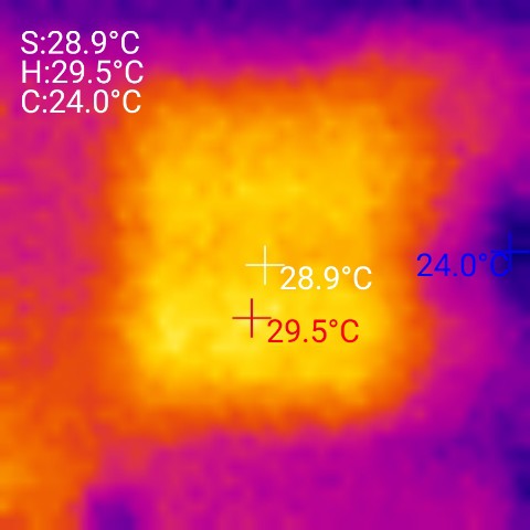
And the temperature of the battery was 29.5 degrees: