Kevin Santo Cappuccio
Hackaday Prize 2023 Entry Video
If you don't want to read through my walls of text, this video should give a good general overview of what this thing can do.
If you have one or want to hang out with people who do, check out the Jumperless Forum or the Jumperless Discord
Deets
The connections are real and fully analog (-8V to +8V, up to around 1 MHz before signal quality starts to degrade) instead of cheating with some measure-then-simulate setup, although you can do that too if you want to simulate a memristor or to send jumpers over the internet.
Currently, the best way to make connections is using Wokwi while running the Jumperless Wokwi Bridge app on your computer. It's a Python script and command line interface that automatically pulls any changes you make to your Wokwi project and sends them to the Jumperless.
Here's a video of me connecting an OLED display to an Arduino
It also passes through all the serial communications to and from the Jumperless so you can use the text-based menus to do things like running the wave generators, measuring current/voltage, and looking debug output on the Jumperless directly at the same time.
The latest firmware update now has the Jumperless show up as 2 USB devices, so you can connect the second one to the Arduino Nano and flash the firmware and communicate via Serial through one USB cable as if they were both plugged in separately. You can also route the UART Tx and Rx lines anywhere and talk to things just like you would with one of those cheap USB-Serial boards. More details about that here.

Pretty soon there will be an Arduino Library where you can make connections and measure stuff with an API that will look something like jumperless.connect(row1, row2); or jumperless.measureVoltage(row); that can either be run on the Arduino Nano (sending commands via UART to the RP2040) or the Jumperless itself.
Hopefully this will allow people to write cool stuff for the Jumperless to do that I haven't even thought of and wouldn't be possible on a regular breadboard.
Also there will be a Python Module that does the same stuff as above, which can either be run in an onboard MicroPython interpreter or on a computer.
Here's another video of me using the Jumperless to figure out the pinout of an LED matrix. I'm actually not faking it in this video, I couldn't find a datasheet.
Firmware and stuff
The Jumperless is controlled by an RP2040 and can be programmed exactly like a Raspberry Pi Pico. I spend every waking second of my life working on the firmware so there will be frequent updates. There are prebuilt UF2 files on Github under Releases, so whenever there's an update, just hold the USB BOOT button while plugging it into your computer (with the included pink glittery USB Mini cable,) then drag that UF2 file into the drive that pops up and you're good to go.
The whole thing is open source so you can also edit/fix the firmware however you like (and please submit a pull request on Github to share your fixes)
DACs and Revisions
Rev 3.1 is the current revision.
Revision 2 uses 2 MCP4728 12-bit I2C DACs, which work great for setting voltages to be used as an adjustable power supply, but I2C isn't fast enough to send clean waveforms above ~100Hz.

Revision 3.1 now uses a single MCP4822 2 channel SPI DAC, which is fast enough to make waveforms well above 400KHz. So you could feasibly use the onboard DAC as a Max8 or plugData output, and route the audio output to the breadboard and mess with it in hardware and even send it back in as an input. The software to do that hasn't been written yet but with the upcoming Python Module and Arduino API, it shouldn't be too difficult pull off.
Both of these revisions have their DACs buffered through an LM272D High Power (1A) op amp. Obviously 1 amp would blow this thing up, the power supplies couldn't handle it, and it would go way over the current limit for the crosspoint switches. But the outputs of the buffered analog voltages are broken out to pads in the top corner, so you could drive a smallish speaker directly form that if you wanted to.
The +-8V DAC output is hardwired to one of the 2 INA219 current/voltage sensors so you can always see how much current is being drawn. The other INA219 is routable anywhere on the breadboard.
If you blow something up on this board for whatever reason, just let me know. I'd be happy to repair it for you for free or walk you through the repair and send you the parts.

For synth/music people
I'll add some relevant info for the more synth/music related stuff here.
First of all, a lot of the earliest, in-depth discussion about trying to make something like this came from a ~200 page thread on some synth forum that eventually fizzled out (I'll try to find the link.) So I have the synth community to thank for some of the early groundwork on this.
What's especially relevant for you guys are the DACs and ADCs. Revision 3 has an MCP4822 12-bit DAC where one output is level shifted with a beefy power op amp to +-8V and the other to 0-5V. I switched to that from 2 MCP4728s (they're I2C, so you can only get like 100Hz cleanly) so it can output frequencies well above audio range, up to ~400Khz.
The ADCs are the built in (12-bit, 500ksps) ones from an RP2040, double buffered and level shifted to the 0-3.3V the RP2040 can handle. One of them is shifted to read +-8V, the other 3 are 0-5V.
One way I envision this could be used for synth stuff, is setting the Jumperless as an output and an input from max8 or puredata, so you can do some stuff there, send it to the breadboard, mess with the signal in meatspace, and then send it back to the computer. Basically making this thing a filter (or whatever it's called, I'm not a musician) that just happens to be a physical breadboard.
Or another way to use this would be to sequence modular synth connections or guitar pedals with a control signal or something. Like having patch cables that can be swapped around really fast (it takes ~30 microseconds to make/break connections) and do it programmatically. The connections can handle +-8.5V and seem to be good up to 1MHz, so it should handle most signal levels (please let me know if that's wrong.)

If you want to play around with those buffers in Falstad Circuit Sim, click here.
Power supplies
The switch on the upper left controls the rail voltages, if you look at the side of the building in the logo, you'll see the settings; +-8V, 5V, and 3.3V. If you set it to +-8V, the top positive rail will be ~+8V and the bottom positive rail will be ~-8V. Otherwise, they will both be the same, either 5V or 3.3V. The negative rails are permanently tied to Ground.

Temper your expectations
Although Jumperless is made with love, it's not a precision instrument, the connections it makes go through CH446Q crosspoint switches and do have some resistance, about 75 Ohms total for a connection and resistance is matched to within 5 ohms for every connection. It sounds like a lot, but in practice it doesn't seem to have a noticeable effect on most circuits that one would build on a breadboard. It also sort of acts like a current limit to keep you from accidentally frying stuff.
If you want to get the resistance lower, you can make redundant connections to halve it each time (running that 75 Ohms in parallel with another 75 Ohms.)
Also temperature apparently has an effect on Ron, the colder it gets the lower the resistance. So if you care, turn the LED brightness down (the generate a good deal of heat) or put the whole thing in a tray of liquid nitrogen.
Worst case, it's still a breadboard and although it's called Jumperless, that's not a rule. You can run jumpers the old fashioned way.
There's also a maximum rated current for the crosspoint switches, it says 15mA per connection and 100mA per chip. I have run 200mA through a single connection for a few minutes without issues, but of course be aware of that.
I'm giving you permission to take the Absolute Maximum Ratings for the CH446Q with a grain of salt. If you fry one, I'll repair it for free. The chips are super easy to swap out with a hot air gun. If you think you're going to fry these chips regularly (it's actually surprisingly hard to do), and have access to a hot air station, let me know when you place the order and I'll throw in a few extra CH446Qs in the box so you can replace them yourself.
For firmware, occasionally there are some arrangements of connections that the pathfinding code trips up on and can't find a path for. If that happens to you, please screenshot the connections and send it to me or open a Github issue. I can usually fix those issues within a day, but the hard part is finding those arrangements that cause issues.
One day when I decide to make my own custom silicon for this, it can be made with beefy power MOSFETs to get it close to a perfect connection. But for now, I have to work with ICs that already exist.
Just for fun, here's a crazy sped-up video of me routing this board:
If you're a l33t hacker, you can even type in netlists by hand. For example,
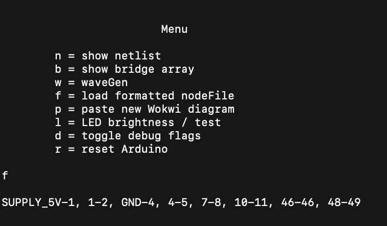
will make this happen:
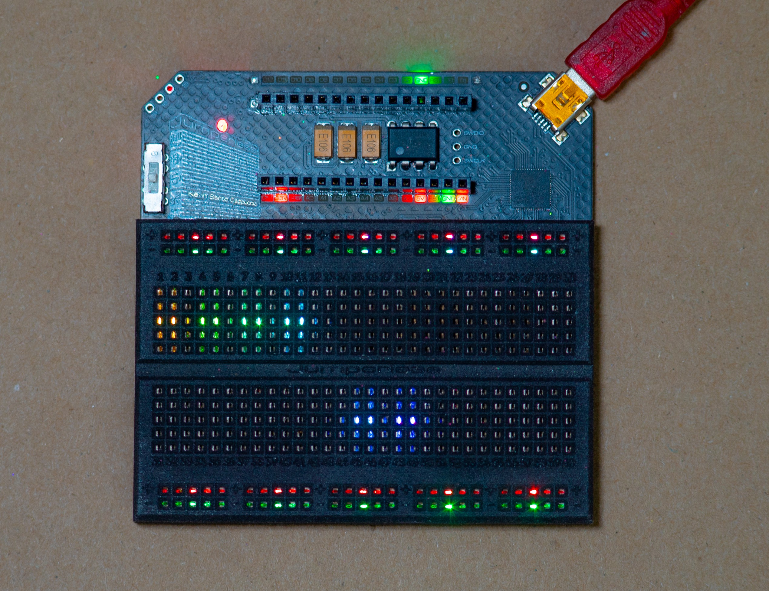
So you can easily write any script you like to make connections this way.
You mean an FPGA?
No, not at all, shut up. I could go on forever about the differences, but the main thing is that FPGAs are really sensitive to input voltages and really only do digital signals. Also FPGAs don't actually route signals, internally they're a grid of lookup tables that do logic operations. So a signal coming in isn't really "sent through" so much as it's copied with a logical NOTNOT (unchanged) gate, that's great for combinatorial logic, but not for analog stuff.
Also quickly throwing together a breadboard circuit in an HDL would take ungodly skills.