This projects is an hardware adaptation of a firmware based RGBW lamp. With few (a lot of) modifications it has became an huge FPGA based project.
How is made this lamp
This lamp uses an Arduino Duemilanove board, which controls 4 power LEDs, for the red, green, blue and white shades. It can be made on true 8 bit colors, but due to FPGA and memory constraints, it runs on 512 pure colors (3 effective bits per color) and on overall 4096 colors if white shades are used too. The board handle the user buttons of the eventual data stream from a PC in order to control the lamp.
The FPGA runs all the calculations that were made originally on the Atmega (which was able to represent 16.7M colors), so that the overall code is actually now less than 1024 kB. In the FPGA I tried to not implement any explicit LUT/RAM/EEPROM or any other type of memory, just raw logic.
I decided to go forward with this implementation because it is not yet meaningless, but educational (at least for myself) since the challenge is related to the code size, but not the overall (here ridiculously increased) cost. In this way I have found a way to use my new Lattice FPGA.
All the debounce is made as much possible in hardware to avoid any code.
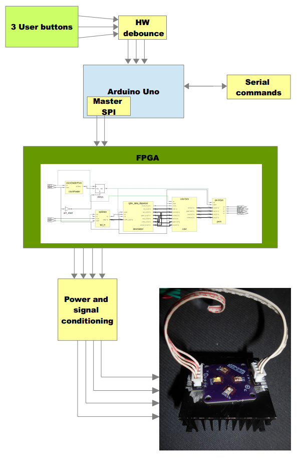
System block diagram
![]()
Inside the blocks are present the following modules, better described in the HW project log:
- Lattice ICE Stick (iCE40 FPGA)
- Arduino Duemilanove (or Uno)
- Op-amps based Schmitt trigger for the input debounce (see Github links)
- Self assembled switching LED drivers (see Github links)
How it works
Buttons and the SPI protocol
The input is made by 3 buttons: mode, up and down. With mode, you can sweep from the white saturation, color selection, intensity.
With the up and down buttons, according to the mode selected, the
perfect color can be chosen, starting from the color, then adjusting its
white component and finally the intensity.
The atmega handle the color selector signal, the white saturation and the uses the SPI protocol to communicate with the FPGA. This is based on a Lattice iCE40, which implements the following designs, better described in the logs:
- SPI slave implementation
- Clock prescaler
- Data deserializer
- Color generator
- Four channel PWM module implementation
When the user uses the buttons, the data is immediately updated and fed through the SPI. The Atmega sends the following serial data:
- sync char (1 byte),
- intensity (1 byte),
- color selecor index (1 byte),
- red (1 byte, not currently used),
- green (1 byte, not currently used),
- blue (1 byte, not currently used),
- white (1 byte),
- mode (1 byte, not currently used)
Serial protocol
When a command is received from the serial interface of the Arduino, the Atmega instruct, using the SPI previously described, the FPGA to switch to the full slave mode and then represent directly the red, green, blue and white received from serial.
The protocol allow to handle and filter away any spurious character, reaching a good dependability on the communication. This is already used in my previous project.
Quoting what I have already written in my previous project, it consist in an array of 18 bytes sent from a master PC or device (over serial/USB) made by the following sequence, from the first to the last byte sent, MSB to LSB:
[StartChar] [CTRL#00] [CTRL#01] [R#0] [R#1] [G#0] [G#1] [B#0] [B#1] [W#0] [W#1] [INT#0] [INT#1] [RES#00] [RES#01] [RES#10] [RES#11] [EndChar]
Where each byte is represented from LSB to MSB, the data is sent using UART (8 bits, 1 Start + 1 Stop bits, no parity).Here below is listed the meaning of each byte:
- StartChar: the char used to discriminate a begin of transmission after startup, or a StopChar, after a timeout or any subsequent StartChar in case of line issues
- CTRL#00/#01: The combination of characters reserved for any auxiliary command. #00 is the MSB, #01 the LSB.
- R#0/#1: channel Red data (from 0 to 0xFF). #0 is the MSB, #1 the LSB.
- G#0/#1: channel Green data (from 0 to 0xFF). #0 is the MSB, #1 the LSB.
- B#0/#1: channel Blue data (from 0 to 0xFF). #0 is the MSB, #1 the LSB.
- W#0/#1: channel White data (from 0 to 0xFF). #0 is the MSB, #1 the LSB.
- INT#0/#1: intensity which is applied to the RGBW channels (from 0 to 0x64 [100% in decimal]). #0 is the MSB, #1 the LSB.
- RES#00/#01: reserved byte for any further necessity. #00 is the MSB, #01 the LSB.
- RES#10/#11: reserved byte for any further necessity. #10 is the MSB, #11 the LSB.
- EndChar: the char used to end the transmission and call the command interpreter on the receiver (Lino).
Of course, this is a feature that can be used from any tool. I simply
tried with one of mine that I had written in Python, but it is not part
of the submission. It is present in the links.
Switching from serial mode to the user mode and viceversa
The conversion from the 2 chars to a single hexadecimal number is made on the fly on the same vector in order to save space in the Atmega. If a button is pressed, the Atmega will give the control to the user, up to the next fully received serial frame. So, switching between the serial mode and the user buttons mode is made just by pressing any button or by sending a complete frame over serial.
The last mode will take over the previous one, but all the
data of the last mode is kept in the Atmega's memory so that when the
user will press a button, the previous setting is restored.
 Enrico