Since the last log I've received my first prototype boards. (This one accommodates the RP2040 DVI feather and the logic chips I need.
This is probably the most disastrous pcb I've received to date. There were multiple problems and you can see some of the bodge wires. There are others on the back.
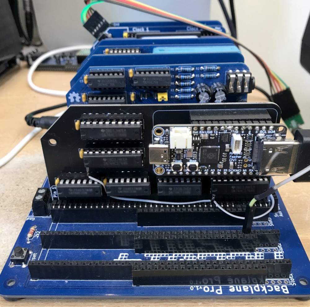
At least it gets rid of the breadboard. I have only ever bought cheap breadboards and leads, so my breadboards are always sketchy (when it's working, don't touch it!)
Besides the ID10T errors, my system for providing the status register didn't work. I didn't breadboard it, but should have done because I would have found one glaring omission.
A revision of the board is on the way, and that should allow me to (at least) provide the most significant bit of the status register. In the meantime, my programs are having to avoid reading that register (J B Langston's library uses that register for the port detection and some demos use it for timing and/or drawing during the vblank. The bit is set to one when the vblank starts and reset to zero when the register is read).
On the software side, I've implemented sprite functionality. Well, so far just the 16x16 unmagnified mode, but the others should be simple to add now. This is working fine (see video below). One interesting point is that my code will display all 32 sprites on a scanline if required. I have to actually add the code to stop it at four, in order to match the TMS chip (and then set the 'fifth sprite' stuff in the status register - I'll come back to that).
So the question is whether to leave it open, allow my board to display all 32 sprites on a line - which is an enhancement to the original chip's functionality. Is that likely to break existing software? (I think that's unlikely - software is likely to check the 'fifth sprite' bit and take action to work around the problem when that happens. Anything that does this should continue to run, unaware that more sprites are being displayed on a row than should be possible.)
My current design allows for my software to control all bits in the status register but at present I'm only handling the 'F' bit (vblank). I will need to use more GPIO pins for this.
Another problem that's come to light is that software wanting to read VRAM may be a bit more common than I thought. I encountered this in the demo in the video below. I used the plotPixel call in J B L's tms library to draw the starfield and it didn't work as expected. It turns out that it calculates the relevant byte in vram, reads it and then uses 'or' to plot the pixel (or 'and' to unplot the pixel). It occurs to me that any software that draws or plots probably does the same.
I had intended to stop short of reading vram (because of a technical reason - the RP2040 isn't fast enough to respond to a port read. At least not with CPU at 7 Mhz. At least I don't think so.)
I now want to do this and I have devised a way to do it, it'll just need a bit more logic and more GPIO pins.
This and the other 6 bits of the status register add up to more GPIO pins than I have available with the feather, which is a real shame.
One option is to use a regular Pico with a DVI sock or similar. But I didn't really want to do that because it'll look really messy. (The feather's black colour is a real plus.) I haven't yet found a RP2040 board with DVI and more GPIO exposed than the feather. Please tell me if there is one.
So I'm going to go ahead with something I've wanted to do for a long time, which is to design my module with a RP2040 chip and supporting components directly on the pcb, rather than use a RP2040 dev board like the Feather or Pico.
The video below shows the picture from my current prototype, with a demo running on the RC2014 that puts 16 sprites on the screen at once, over a background in bitmap mode. I've adapted this from a classic demo that bounces one of these globes around the screen using 2 overlaid sprites - you'll find that one in J B Langston's TMS9918A repository.
With thanks to a follower who sent me this link: https://github.com/tursilion/bitmaptest which is a tool to test various modes and sprites on the 9918 chip. This will be useful for testing.
Discussions
Become a Hackaday.io Member
Create an account to leave a comment. Already have an account? Log In.