 ElectroBoy
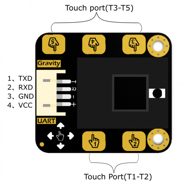
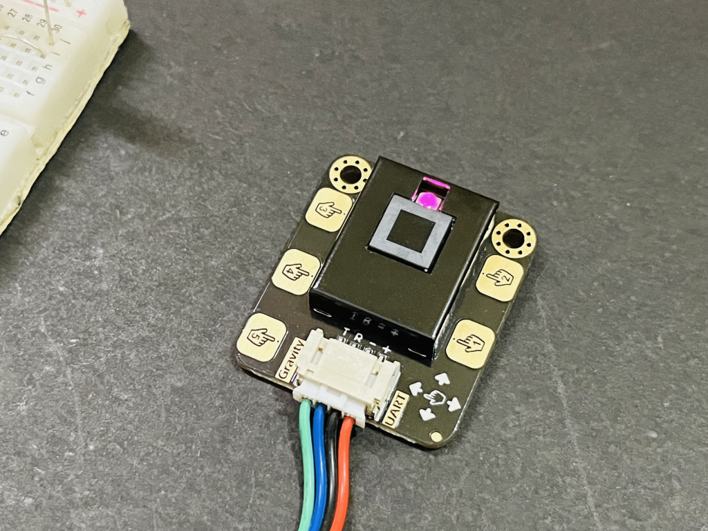
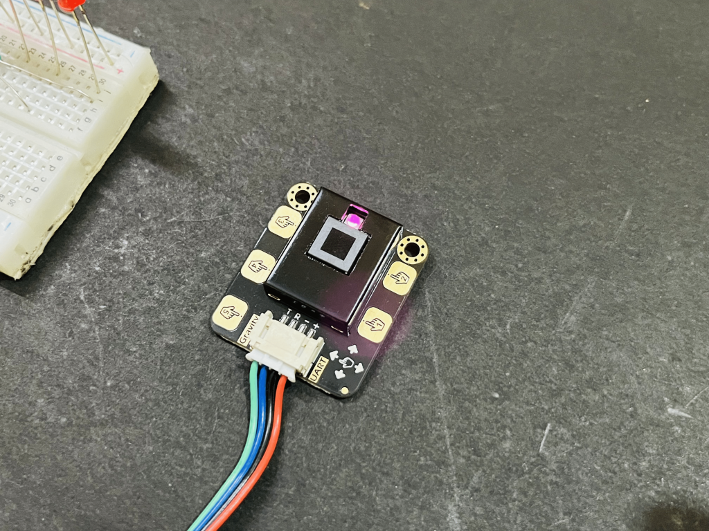
This sensor module integrates gesture recognition and touch detecting functions in one piece, and provides an adjustable detection range within 0~30cm. When connected to your microcontroller, it can detect 5-way touch signal and 7 kinds of gestures: move left, move right, move forward, move backward, pull up, pull down, pull and remove.
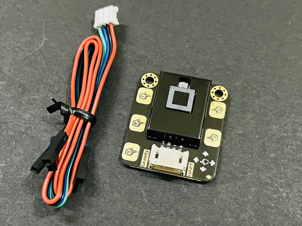
Besides, the sensor is also equipped with the function of auto-sleep and wake up. The module comes with the gesture recognition algorithm and provides simple and reliable data output. Use the sensor to directly communicate with upper computer or micro-controllers like Arduino and Raspberry Pi via serial port.
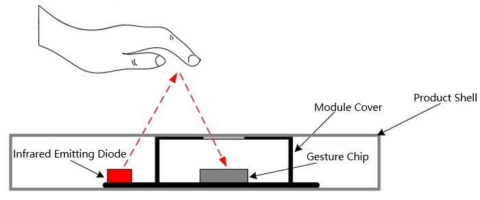
It works on the principle of infrared detection, the hand motion is monitored using an infrared led and sensing system. The infrared light strikes with hand and go to the sensing unit for proper interpretation. Infrared (IR) light is comes in invisible spectra and the sensor used in this mechanism is very selective because IR is also present in the sunlight that's why sensor is less effective in outdoors.
Application of gesture and touch:
The onboard 5-way touch pad on the sensor can be directly used to detect touch, or you can extend the touch pad with wires to make it perfectly fit in your application. The outer shield for the sensor retains the advantages of Gravity series as well as makes the sensor more durable. This sensor can be used to make smart lamp, DIY intelligent car, or used in interactive projects requiring gesture recognition.
Features:
- Power Supply: 3.3V - 6V (recommend 5V)
- Output Voltage: 0 - 3.3V
- Operating Current: about 56.3mA
- Sleep Mode Current: about 40uA
- Output: TTL serial port
- Serial Protocol Format: 9600 band rate; 8 data bits, no parity bit, 1 stop bit
Note:
Abnormality might occur when using the module in strong sunlight condition due to its working principle;
When powered down, the sensor will be initialized automatically and the previous setting will be invalid.
When sending byte continuously, there should be at least 200us time interval between the end of the last byte and the starting of the next byte; The sensor can receive/transmit data only in working state, while for processing data, we must make the sensor stay in non-working state. That is to say, if there is an object over the sensor when receiving/transmitting data, we need to move it away for completing the following settings.
Normal Settings and functions:
- Default function when powered on: no sleep, 5-way touch, detecting height: 15cm.
- The default detecting height is 15cm, higher height detection needs to be set by yourself.
- Keep a normal speed when gesticulating to let the sensor better understand your gesture.
Code functions:
1) Set the sensing height (default 20cm when powered on)
Example: DFGT.setGestureDistance(20);---Unit(cm) Max height: 30cm
2) Set the sleep enablement or enter auto-sleep mode (sleep mode disabled when powered on)
Example: DFGT.setSleep(4);---unit(s)
3) Set gesture sensing enablement (all the seven gestures can be recognized when powered on)
Example(1) DFGT.enableFunction(DFGT_FUN_ALL);---enable all gestures sensing fuction

Example(2) DFGT.disableFunction(DFGT_FUN_RIGHT | DFGT_FUN_LEFT);---disable sensing function of part gestures

Example(3) DFGT.enableFunction(DFGT_FUN_RIGHT | DFGT_FUN_LEFT);---enable sensing function of part gestures
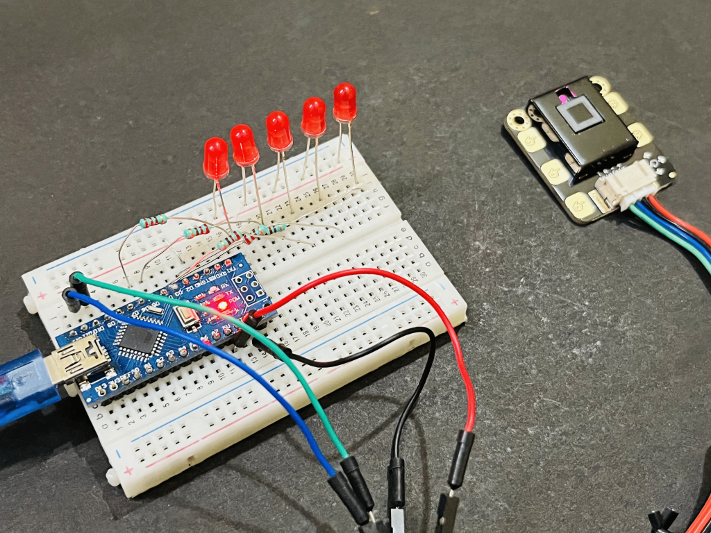
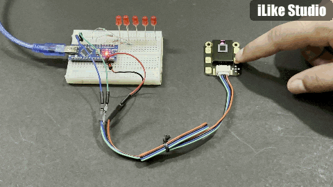
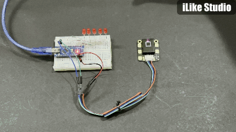
Components Required:
Led 5mm red
- 220ohms resistor
- ARDUINO NANO
- Breadboard
- Custom PCB design from JLCPCB
Circuit diagram:
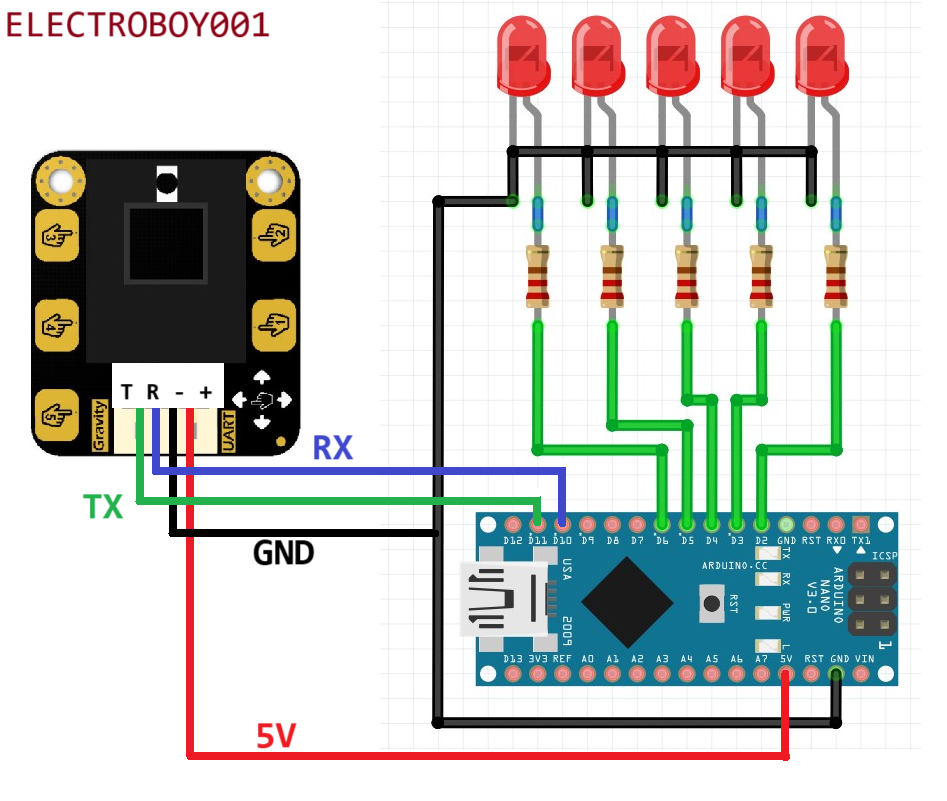
The 4 red LEDs are connected to the digital pins of the Arduino NANO. The gravity sensor is connected to the digital pin 10 and 11. Rx of the sensor is connected to the Tx pin and Tx of sensor to Rx which is defined in the software serial of the Arduino. Different tasks are assigned to the LEDs based on the actions and functions defined in the Arduino program. The connections are very simple, to power up the circuit an external power supply of 5v @1amp can be used.
You can design the PCB whenever doing any project with this kind of sensor and I always suggest to use JLCPCB PCB manufacturing services, they provide the best services in good prices. You can try 5pcs of 2-layer PCB in just $2 and SMT assembly is starting just from $8.
Simple testing code:
Here the readings of sensor also got printed on the serial monitor through serial port of Arduino (UART) and the gravity sensor also support UART interface. That’s why in the Arduino code software serial is used RX pin is named as D10, Tx as D11. Gravity sensor has a different library which can be downloaded from here and can be directly included in the Arduino IDE in ZIP format.
// Modified by Sagar saini

#include "DFRobot_Gesture_Touch.h"

#ifdef __AVR__
  SoftwareSerial    mySerial(/*RX*/10, /*TX*/11);
#elif defined ESP_PLATFORM
// ESP32:IO16 <--> TX:sensor
// ESP32:IO17 <--> RX:sensor
HardwareSerial mySerial(1);
#endif

// init sensor object, request write and read function
DFRobot_Gesture_Touch   DFGT(&mySerial);

int led_1 = 2;
int led_2 = 3;
int led_3 = 4;
int led_4 = 5;
int led_5 = 6;

void setup()
{
  Serial.begin(115200);
  pinMode(led_1, OUTPUT);
  pinMode(led_2, OUTPUT);
  pinMode(led_3, OUTPUT);
  pinMode(led_4, OUTPUT);
  pinMode(led_5, OUTPUT);

  // suggest default value
  DFGT.setGestureDistance(20);

  // enable all functions
  DFGT.enableFunction(DFGT_FUN_ALL);

  // disable function test
  //DFGT.disableFunction(DFGT_FUN_RIGHT | DFGT_FUN_LEFT);

  // enable function test
  // DFGT.enableFunction(DFGT_FUN_RIGHT | DFGT_FUN_LEFT);

  // set auto sleep time out, in sleep mode, something approach will wake it up
  // DFGT.setSleep(4);

  Serial.println("simple Gesture!");
}

void loop()
{
  // get an event that data saved in serial buffer
  int8_t rslt = DFGT.getAnEvent();

  if(rslt != DF_ERR)
  {
    // disable auto sleep
    // DFGT.setSleep(DFGT_SLEEP_DISABLE);
    switch(rslt)
    {
      case DFGT_EVT_BACK:
        Serial.println("get event back");
        digitalWrite(led_1, HIGH);
        break;
      case DFGT_EVT_FORWARD:
        Serial.println("get event forward");
        digitalWrite(led_1, LOW);
        break;
      case DFGT_EVT_RIGHT:
        Serial.println("get event right");
        digitalWrite(led_2, HIGH);
        break;
      case DFGT_EVT_LEFT:
        Serial.println("get event left");
        digitalWrite(led_2, LOW);
        break;
      case DFGT_EVT_PULLUP:
        Serial.println("get event pull up");
        all_on();
        break;
      case DFGT_EVT_PULLDOWN:
        Serial.println("get event pull down");
        all_off();
        break;
      case DFGT_EVT_PULLREMOVE:
        Serial.println("get event pull and remove");
        all_off();
        break;
      case DFGT_EVT_TOUCH1:
        Serial.println("get event touch1");
        digitalWrite(led_1, HIGH);
        break;
      case DFGT_EVT_TOUCH2:
        Serial.println("get event touch2");
        digitalWrite(led_2, HIGH);
        break;
      case DFGT_EVT_TOUCH3:
        Serial.println("get event touch3");
        digitalWrite(led_3, HIGH);
        break;
      case DFGT_EVT_TOUCH4:
        Serial.println("get event touch4");
        digitalWrite(led_4, HIGH);
        break;
      case DFGT_EVT_TOUCH5:
        Serial.println("get event touch5");
        digitalWrite(led_5, HIGH);
        break;
    }
  }
}

void all_on(){
  digitalWrite(led_1, HIGH); // write your own functions to control digital outputs
  digitalWrite(led_2, HIGH); // or to do something else with the gestures
  digitalWrite(led_3, HIGH); // now it is upto you how you play
  digitalWrite(led_4, HIGH);
  digitalWrite(led_5, HIGH);
  delay(100);
}

void all_off(){
  digitalWrite(led_1, LOW);
  digitalWrite(led_2, LOW);
  digitalWrite(led_3, LOW);
  digitalWrite(led_4, LOW);
  digitalWrite(led_5, LOW);
  delay(100);
}
Functions used:
I initialize all the functions, so that all movements and touch actions can be triggered. For this in the Arduino sketch I made an external function to toggle the Red LEDs connected to the Digital I/O pins. You can download all the schematics and code directly from here.
PCB designs:

I designed a shield to the simple project which I think is a good way to do these. In the shield Arduino Nano is used which is soldered on board and the connections can be made through male headers near it. To display any data it has onboard 128x64 OLED, for digital output it has a buzzer and led. It has optimised power section just supply it with barrel jack from 9-12volts. Order the PCB directly uploading the GERBER files to JLCPCB, Sign-up to JLCPCB using this link and get free PCB coupons of worth $54 for your next order. This link is only applicable to new users.
Testing:
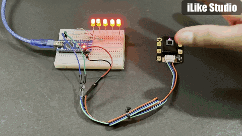
I tested this sensor with 20cm height, no sleep mode and all the functions are active the sensor works perfectly fine in room light, I am not much sure about daylight but when I tried the left right function identification in not too much proper. The best response I got when in sunlight the pull up, pull down, pull and remove functions are used the response is good because in these 3 cases sensor is covered with hand.
The touch response is very good and quicker than any other touch sensor. The touch wires can be extended and external copper pad can be designed for any applications. I made this simple code to only toggle LEDs via controlling digital outputs of Arduino, you can write your own functions to do something else, now it's up to you how you play. Make sure to give a try to the JLCPCB SMT assembly and PCB services in very good prices.