 Walter
I want to use a kit for the clock electronics. That needs 12V 1A. I did some testing on the transformer that is in the device, but the voltages are not really suitable. I decided to get a cheap 12V buck converter. Also, I made the decision to not do the build in such a way that you can easily revert to the original device.
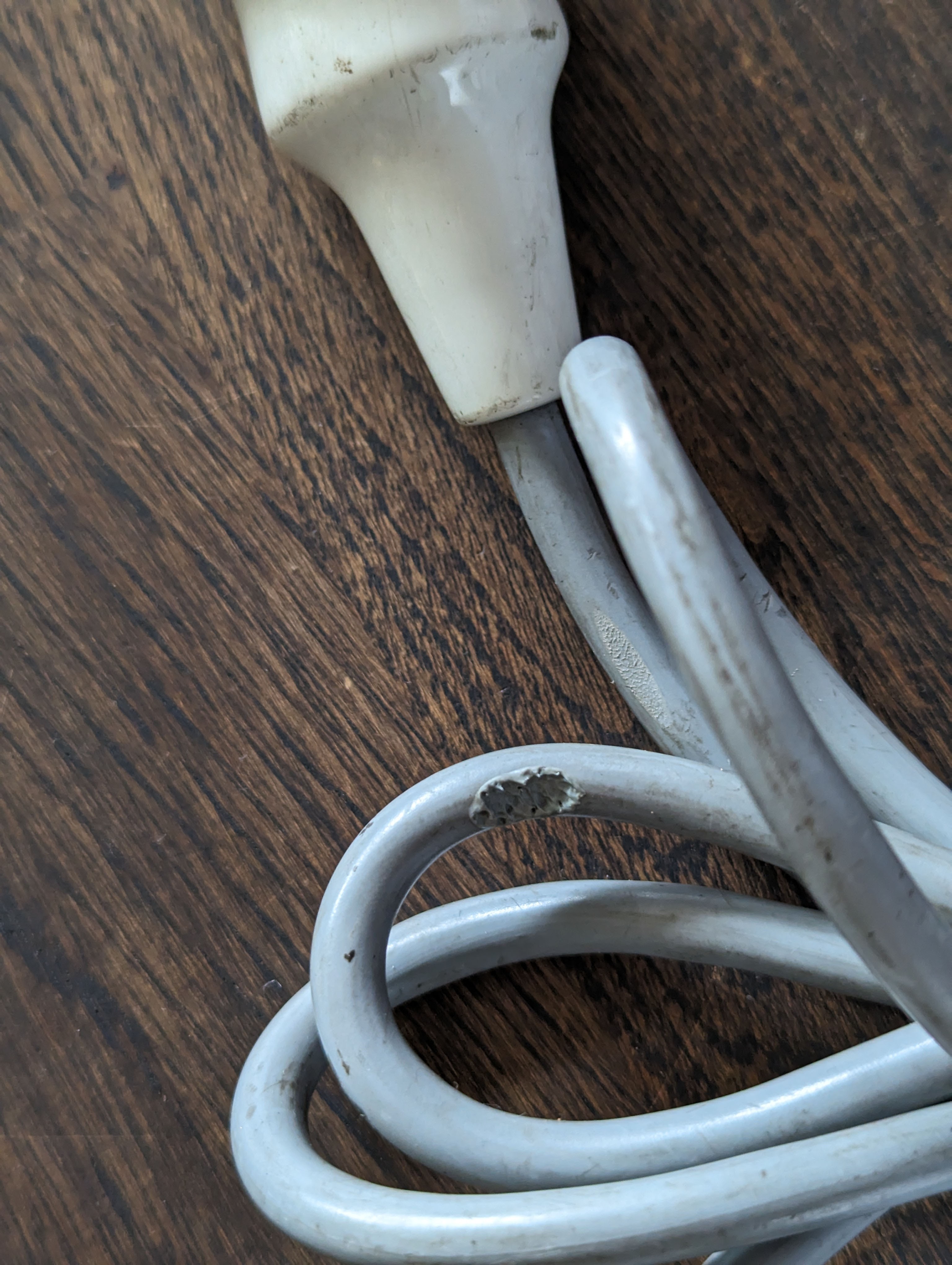
First, the power cable needed to go, as that was damaged.
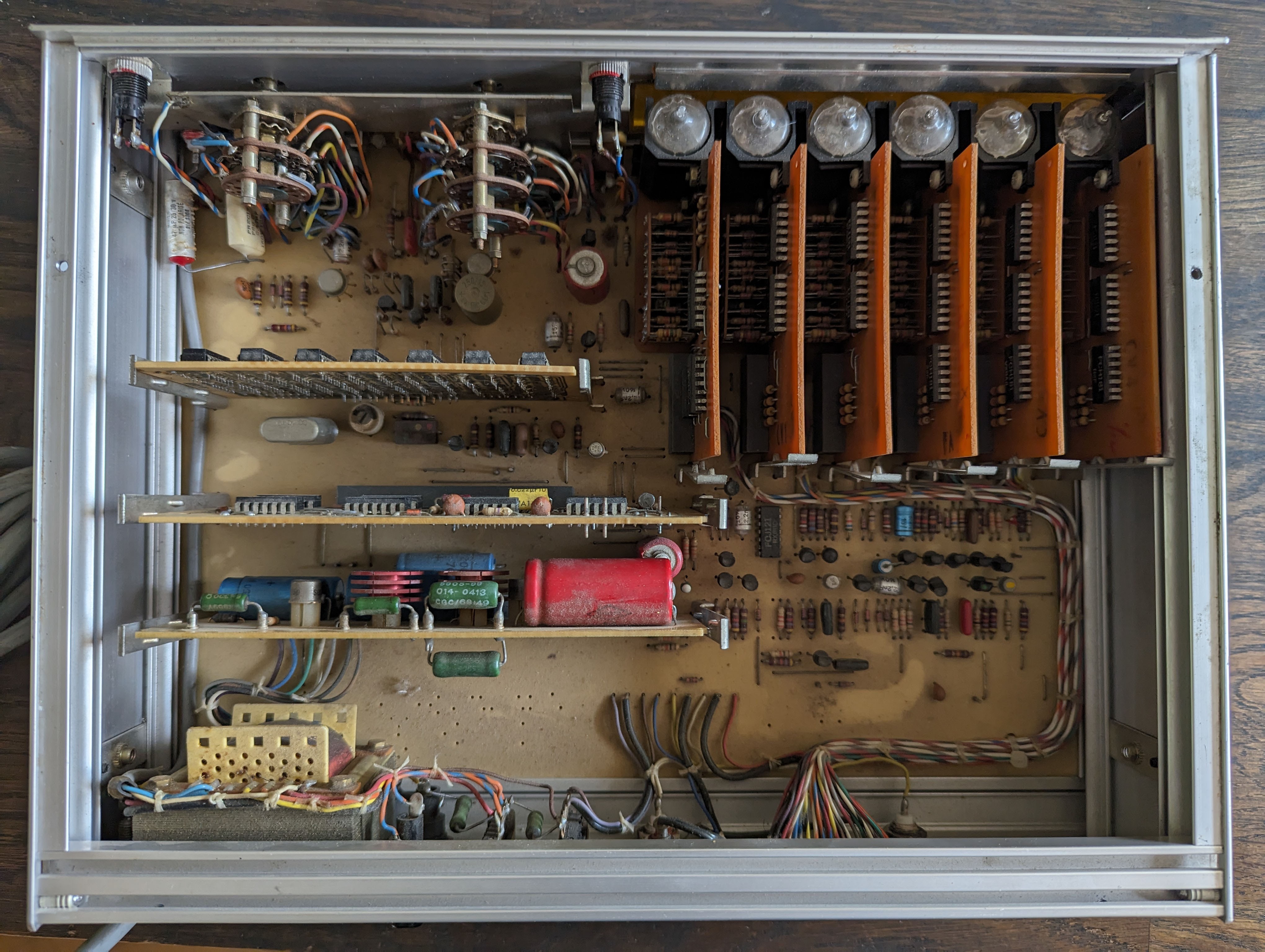
Then, a look inside the Schneider. In there we see a neat arrangement of components. Some are on the main PCB, but there are also modules that are plugged in to the main PCB. Three of them hold some old logic chips, six are the nixie boards.
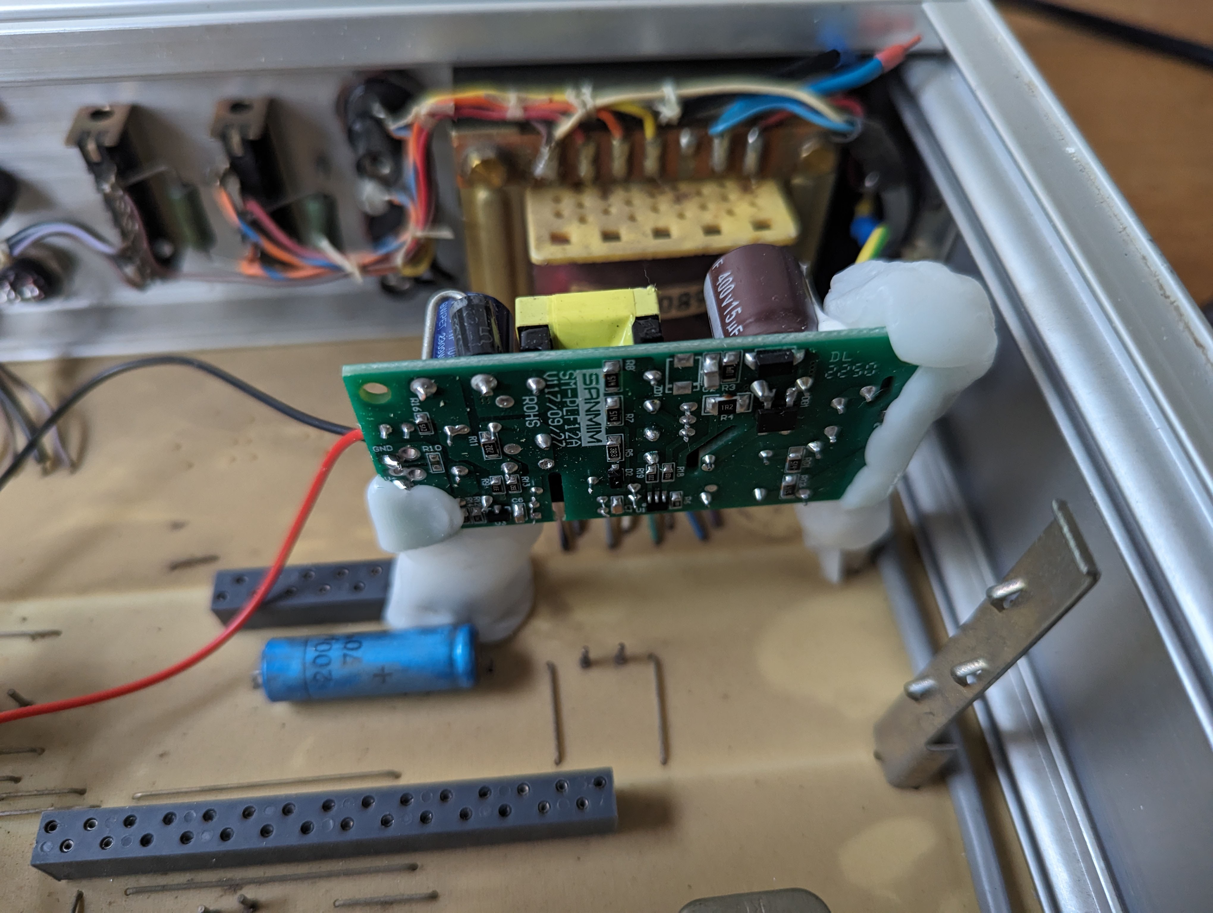
I put in a new power cable, connected ground to the casing, and the mains wires to the buck converter. To securely fix the converter into the enclosure, I again used moldable plastic. The PCB modules have little stands on the side, and I re-used one of those to mount the buck converter upright, away from things that could cause a short.
There's a few things I am contemplating, while waiting for the nixie clock kit to arrive.
- I think of repurposing the display or sensitivity knobs (they are potentiometers with an on/off switch integrated) as main switch, probably the 'display' knob.
- There are 2 lights on the front panel. I could use one to indicate the box is on, but that's not needed as you can see the nixies are on. It would be a shame not to do anything with these lights.. maybe I can use the other knob (the sensitivity knob) to power these lights on or off and set the brightness. The lights seem to be made to run on 9 volts or so.
- I need three push buttons for controlling the clock. I thought about adding three buttons on the back, but I changed my mind and will put 2 on the back (where two BNC connectors currently are) and will use the "reset" switch on the front as the main mode switch.
Discussions
Become a Hackaday.io Member
Create an account to leave a comment. Already have an account? Log In.