 Jorj Bauer
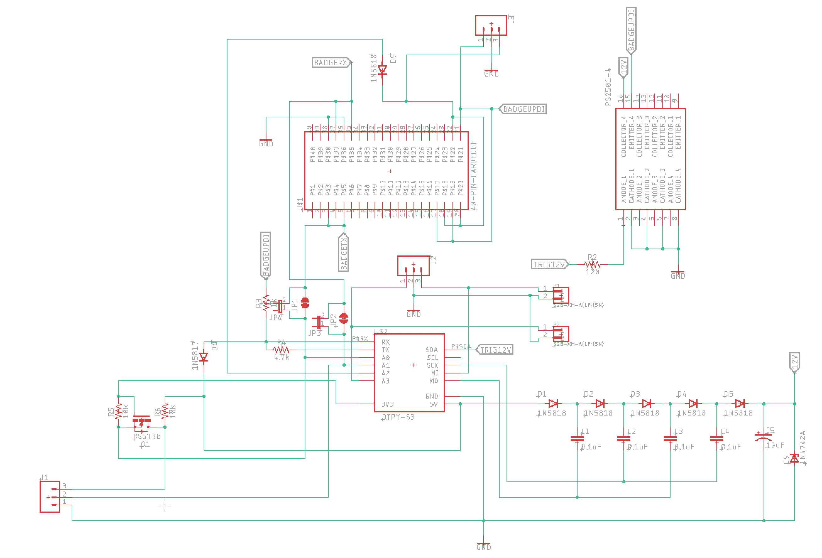
So let's talk about the programming interface. The UPDI programming spec is fairly easy, and I wound up coding an ESP32-S3 so that it could reprogram a badge using UPDI. That meant that the dock could suddenly give firmware updates, which is a great bonus - I'd have a way to reprogram badges at the con, should some bug surface. I already had plans for a public dock, for reasons I'll get in to later - this all aligned well.
But it still triggered debug mode occasionally. Rarely. But once it did, the badge was stuck in debugging mode. Since it's self-powered by its battery, once it's in debug mode it's gonna stay there until something tells it not to be.
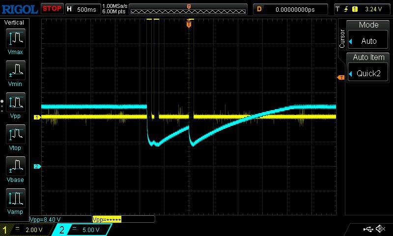
But there's a great feature of the UPDI interface on these Series-0 Atmel devices where you can require a +12v pulse on the UPDI pin to activate it. Some code needed updating in my dock protocol, and I needed a way to generate +12v out of the +5v I was using, but one Dickson Charge Pump later I've got something usable with the parts lying around my house.
The 0.1uF capacitors in the lower-right are fed two out-of-phase square waves from the microprocessor, which build up potential across the diodes; the voltage winds up boosting over the span to somewhere around 13-14v, and the final 1N4742A diode clamps it to 12v. Here you can see it discharging a few +12v pulses and charging back up...
Great! That's #1 sorted.
The power consumption issues took a little while to crack. First, I'd accidentally misread the vendor's specs on the power boost IC, and used resistors one-thousandth the values they were supposed to be. They leaked a commensurate amount of current, and I wound up doing some surgery on Dalek Agatha to figure it out. (This is about when she got her name -- she was a bit of a mystery!)
I cut the power trace from the boost circuit to the ATTiny and measured its current draw - no problem, low as can be. It took a few minutes of puzzling at the schematic to see it...
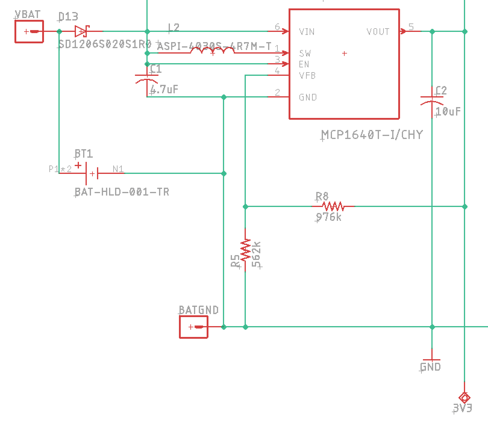
The only logical parts of "why is this drawing so much power" were the resistors; I measured current through them and found that, yes, they were responsible; and started yelling about how the manufacturer's reference schematic was awful before I realized I'd misread it. Whoops, my bad. Runtime jumps from under 2 days to about 4 days, and I'm in the ballpark.
The rest of the win was in software. The general goal was to wake on both a hardware interrupt (if someone presses any button, wake up) and a timer interrupt (wake up periodically to see if we should nag the user to play a game). The combination is pretty easy to set up, but it turned out to be a little tricky to get it in to a lower power state during its power-down time. We'd run through dozens of batteries in the house looking at runtime, running stopwatches to be sure, and when I finally got it right, we jumped from 4 days ... to literal months of runtime.
Now, the final badges will get more use in 3 days than we gave them in those months - but I'm pretty confident that it will last the 3 conference days pretty easily.
Why didn't I just trust the current draw math, you say? These batteries are about 200mAh; it should be easy math to take how many milliamps are being drawn and divide appropriately to see how many hours it would run. There are two problems with that...
First: CR2032 batteries are pretty terrible at high draw. If there are spikes where the battery draws high current, it's going to deplete the battery faster than math would normally dictate. I didn't know how badly that would affect these badges with occasional flashing blinky LEDs.
And second: getting a good measurement of the small amount of current it's drawing turns out to be a bit complicated. On one of my docks I inserted a 6-ish-ohm resistor and measured the voltage across it to calculate the current draw. Even then - with the tolerances of the low-ohm resistor and the measurement of the meter, I wasn't super confident in the numbers.
No, the emperical answer was the one that sold me. This should work...
Discussions
Become a Hackaday.io Member
Create an account to leave a comment. Already have an account? Log In.