 yjmwxwx
Bought some PY32F002AF15P6TU in Lichuang Mall, so in order to test the performance of a simple battery internal resistance tester, the measurement range is divided into milliohm and ohm two gears, milliohm gear measurement range shows 00.00 to 60.00 milliohm, the smallest resolution 0.01 milliohm, ohm gear shows 0.000 to 2.000 ohm, the smallest resolution of 1 milliohm, the measurement of current 20mA. Voltage mainly for single lithium batteries, isolation capacitor selected low voltage, to measure the voltage of the battery to change the amplifier output isolation capacitor.
Can be used to measure the battery internal resistance, capacitance ESR, current sampling resistance.
Hardware
common-positive digital tube (electronics)!
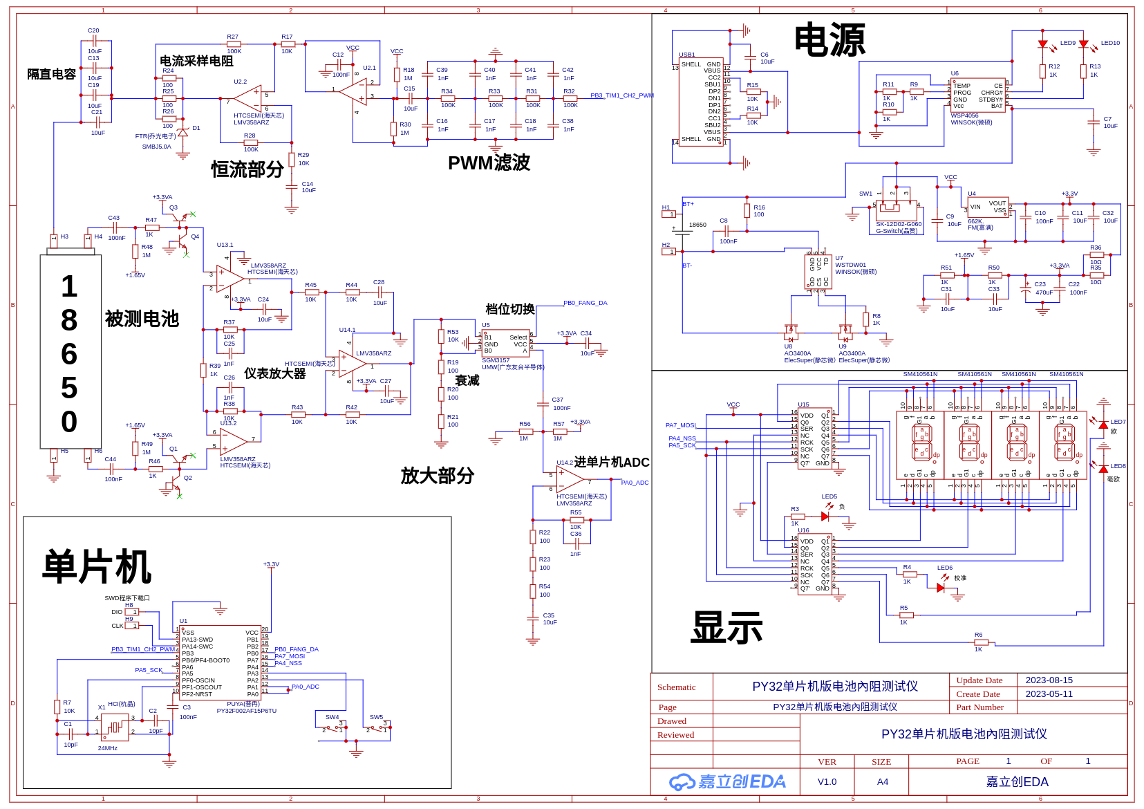
The right side is a common power supply and display part will not speak, the main introduction of the left signal part, microcontroller output all the way to 1KHZ PWM model, after RC filtering into a sinusoidal wave, and then through the c15 isolation capacitor, capacitance behind the lift to VCC/2, in the U2.1 voltage follower into the.

After getting raised to VCC/2 sine wave into U2.2 constant current circuit, the sampling resistor is three parallel 100-ohm resistors, TVS protects the op-amp, and then the 1KHZ AC signal is injected into the battery through four parallel 10uF capacitors.
H3, H4, H5, H6 port connected to the Kelvin four-wire test clip, H3, H5 for the current excitation port, H4, H6 for the voltage signal port, through the C43, C44 100NF capacitance isolation capacitor isolation battery DC voltage only to take out the 1KHZ AC voltage, capacitance behind the lift to 1.65V, four transistors here as a diode, leakage than the diode is small.

Then it goes to an instrumentation amplifier consisting of three op-amps with 21 times amplification.

Then enter the U5 analog switch, sampling first attenuation after the amplification mode to achieve the two-stage switching, the benefit is that the phase shift of the two gears is the same as only calibrate a gear on the line, amplify the end of the direct access to the microcontroller ADC.

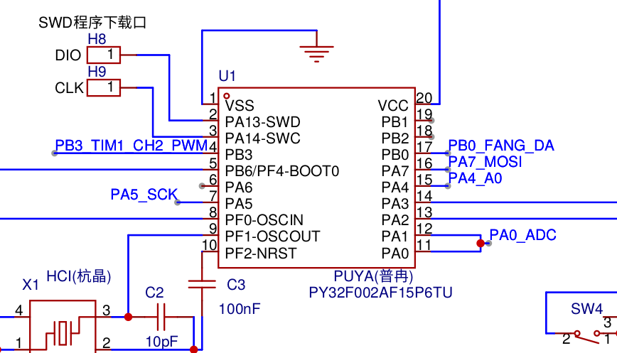
The microcontroller part is relatively simple, PB3 outputs 1KHZ sine wave, PA0 and PA1 are shorted ADC ports, PB0, PA7, PA4 are SPI ports. H8 SWDIO, H9 SWCLK are SWD debug ports for debugging and downloading programs, PA2 and PA3 are key input ports.
SWD debugging port
H8 SWDIO, H9 SWCLK, the other one is connected to GND.
Four-wire test clip port, one clip for amplifier output + and signal think +, one clip for negative and negative.


Software part
The software is written in GNU ARM assembly, compiler ARM-NONE-EABI.
Timer output 1KHZ sine wave, PA0 and PA1 open two channels of ADC sampling, with another timer to set the trigger frequency of 100KHZ trigger ADC sampling, sampling through the DMA transfer to memory, DMA using cyclic mode sampling 1000 points, SYSTICK timer set to 10 milliseconds to interrupt a time, the following code to realize the above said function.
__adc_dma: ldr r0, = 0x40020000 ldr r1, = 0x40012440 @外设地址 str r1, [r0, # 0x10] ldr r1, = 0x20000160 @储存器地址 str r1, [r0, # 0x14] ldr r1, = 1000 @传输数量 str r1, [r0, # 0x0c] ldr r1, = 0x35a1 @ 0x583 @ 5a1 @传输模式 str r1, [r0, # 0x08] _adcchushihua: ldr r0, = 0x40012400 @ adc基地址 ldr r1, = 0x80000000 str r1, [r0, # 0x08] @ ADC 控制寄存器 (ADC_CR) @adc校准 _dengadcjiaozhun: ldr r1, [r0, # 0x08] movs r1, r1 bmi _dengadcjiaozhun @ 等ADC校准 _tongdaoxuanze: ldr r1, = 0x20000000 str r1, [r0, # 0x10] @时钟分频 movs r1, # 0x03 str r1, [r0, # 0x28] @ 通道选择寄存器 (ADC_CHSELR) ldr r1, = 0x8c3 @0x3003 @连续0x2003 @触发0x8c3 @ 0xc43 @TIM3 0x8c3 @0x2003 @0x8c3 str r1, [r0, # 0x0c] @ 配置寄存器 1 (ADC_CFGR1) movs r1, # 0 str r1, [r0, # 0x14] @ ADC 采样时间寄存器 (ADC_SMPR) ldr r1, = 0x05 @ 开始转换 str r1, [r0, # 0x08] @ 控制寄存器 (ADC_CR) str r1, [r0, # 0x08] @tim3chushihua: ldr r3, = 0x40000400 @ tim3_cr1 ldr r2, = 0 str r2, [r3, # 0x28] @ psc ldr r2, = 959 str r2, [r3, # 0x2c] @ ARR movs r2, # 0x20 str r2, [r3, # 0x04] @ TRGO @tim1chushiha: ldr r0, = 0x40012c00 @ tim1_cr1 movs r1, # 0 str r1, [r0, # 0x28] @ psc ldr r1, = 47999 str r1, [r0, # 0x2c] @ ARR @ movs r1, # 0x20 @ str r1, [r0, # 0x04] @ TRGO ldr r1, = 0x6800 str r1, [r0, # 0x18] @ ccmr1 CC2 ldr r1, = 0x10 @ CC2 str r1, [r0, # 0x20] @ ccer ldr r1, = 0x8000 str r1, [r0, # 0x44] @ BDTR @ ldr r1, = 0x100 @ CC2 DMA @ str r1, [r0, # 0x0c] @ DIER ldr r1, = 24000 str r1, [r0, # 0x38] ldr r1, = 0x81 str r1, [r0] str r1, [r3] ldr r4, = 0xe000e010 ldr r3, = 479999 str r3, [r4, # 4] str r3, [r4, # 8] movs r3, # 0x07 str r3, [r4] @systick 开 ldr r0, = lvbo_changdu ldr r1, = lvbo_youyi movs r2, # 200 str r2, [r0] movs r2, # 14 str r2, [r1] ldr r0, = cossin ldr r1, = cos_sin_biao_1k str r1, [r0]
Entering the SYSTICK timer interrupt first uses the DFT to count the real and imaginary parts of 1000 points of data, followed by 200 points each into the sliding filter
_systickzhongduan:        @syzd
    push {r0-r4,lr}
__suan_dft:
    bl __dft
    ldr r2, = shangbi_rr
    ldr r3, = shangbi_ii
    str r0, [r2]
    str r1, [r3]
    mov r4, r0
    ldr r2, = lvboqizhizhen1
    ldr r0, =lvboqihuanchong1
    bl __lv_bo_qi
    ldr r1, = shangbi_i
    str r0, [r1]
    mov r1, r4
    ldr r2, = lvboqizhizhen
    ldr r0, =lvboqihuanchong
    bl __lv_bo_qi
    ldr r1, = shangbi_r
    str r0, [r1]


    ldr r0, = shangbi_r
    ldr r1, = shangbi_i
    ldr r0, [r0]
    ldr r1, [r1]
    bl __ji_suan_fu_du
    ldr r2, = fudu
    str r0, [r2]


    ldr r0, = liangcheng
    ldr r2, = 0x50000400
    ldr r3, [r0]
    cmp r3, # 1
    beq __haoou_dang
__ou_dang:
    movs r3, # 1
    lsls r3, r3, # 16
    str r3, [r2, # 0x18]
    b __systick_fanhui
__haoou_dang:
    movs r3, # 1
    str r3, [r2, # 0x18]

__systick_fanhui:
    ldr r0, = 0xe0000d04
    ldr r1, = 0x02000000
    str r1, [r0]                 @ 清除SYSTICK中断
    pop {r0-r4,pc}
The DFT program is written in as few loops as possible, so it looks very long, I don't know if this will be faster, anyway, there is a lot of space to use up.
Here you get the real and imaginary part of the battery under test two data, first clamp a non-inductive resistor, with ATAN2 calculated phase, and then rotate the angle to 0 degrees, only the real part of the real can be, so as to be unaffected by the inductance of the test line.
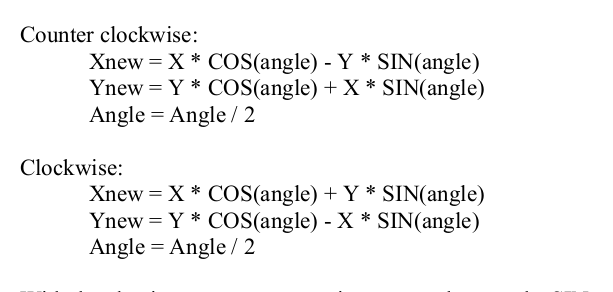
Rotate the phase method, as for ATAN2 and calculate the COS and SIN method see attached cordic.pdf
Calibration Method
Three calibration menus, display P-00 for short circuit clearing, display P-01 for phase calibration, display P-02 for standard resistance calibration.
Press and hold the key to switch gears and then press and hold the other one at the same time to enter the calibration mode, the digital tube displays P-00, press the key of gear plus will switch between P-00, P-01, P-02, two keys a piece of press to exit the calibration menu displays END, press the other key to enter the displayed menu.
P-00 Clamp short circuit, two keys plus or minus to adjust to 0, first adjust the ohm file, two keys a piece of press to enter the milliohm file, adjust and then two keys a piece of press to save to FLASH display END
P-01 clamp the 1 ohm resistor, adjust to the real phase of this resistor, I don't know just adjust to 0, after adjusting the two keys a press to save to FLASH Show END
P-02 clamp the standard resistor to adjust the reading to the same as the resistor, also is the first to adjust the ohm file, two buttons a press to enter the milliohm file, after adjusting and then two buttons a press to save to FLASH Show END
Home quasi-demo video, squatting at home for almost 16 years with poor language skills can not speak Mandarin. If you don't understand, you can click on the subtitles to have automatically generated subtitles.
Milliohm file calibration can use 10 milliohm or a little larger calibration, calibration after the measurement of 0.1 milliohm may be too large, and then use a short circuit to clear the zero adjusted to small on the line.
Calibration method demonstration video
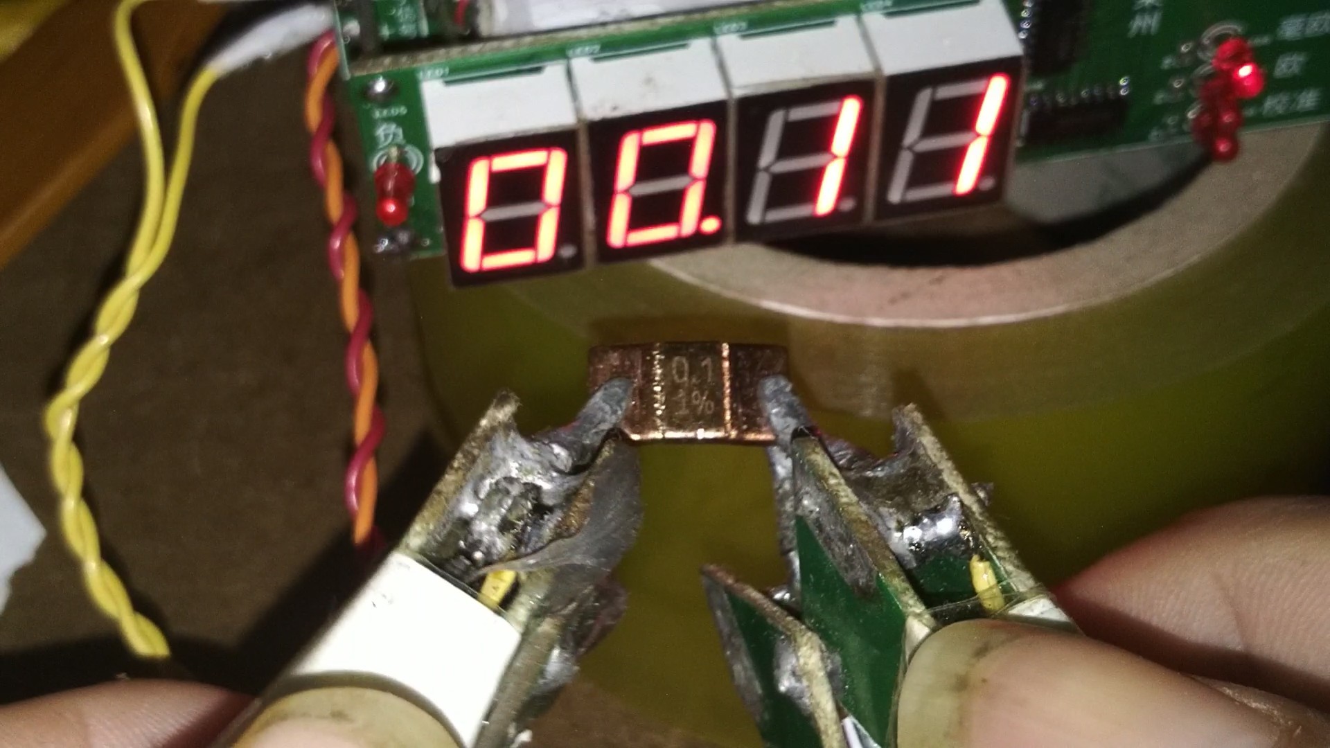
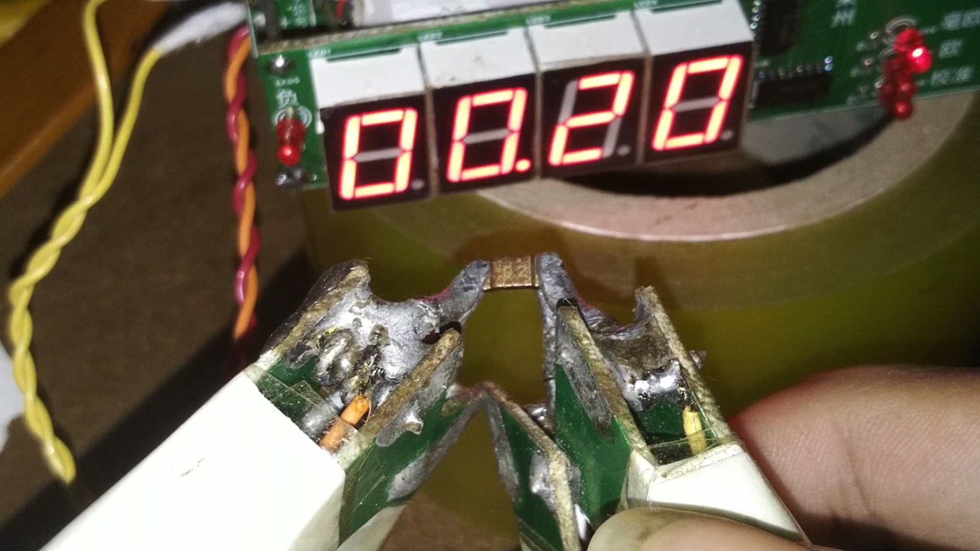
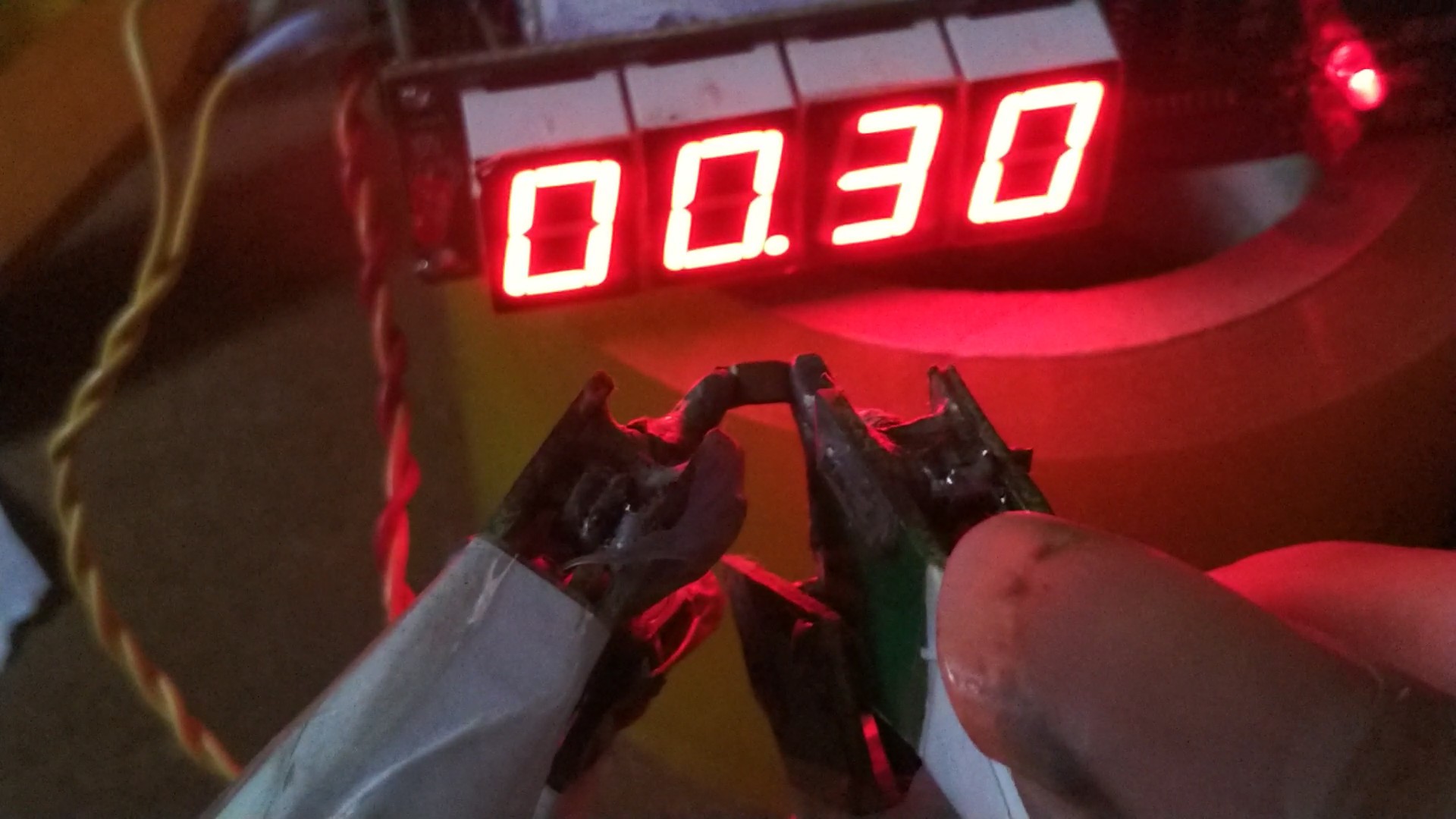
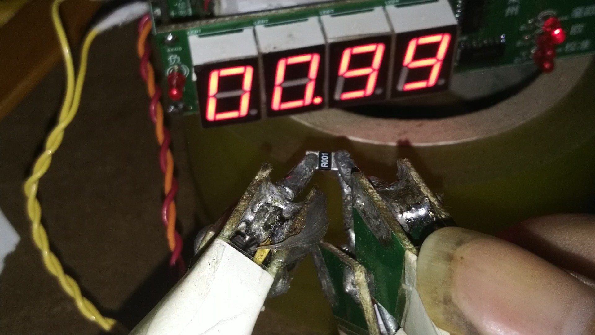
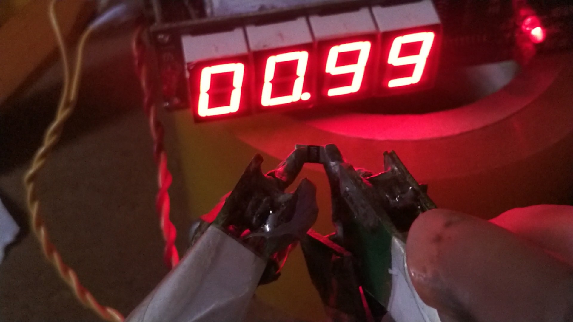
Measured 0.1 mOhm to 1 mOhm resistance
Measure 0.1 milliohm resistance
Measure 0.2 milliohm resistance

Measure 0.3 milliohm resistance
Measure 0.5 milliohm resistance


Measurement of 1 milliohm resistance
COG12864 Display Version Circuit


/led_nei_zu_yi/COG12864_nei_zu_yi/
COG12864 Display Version Program
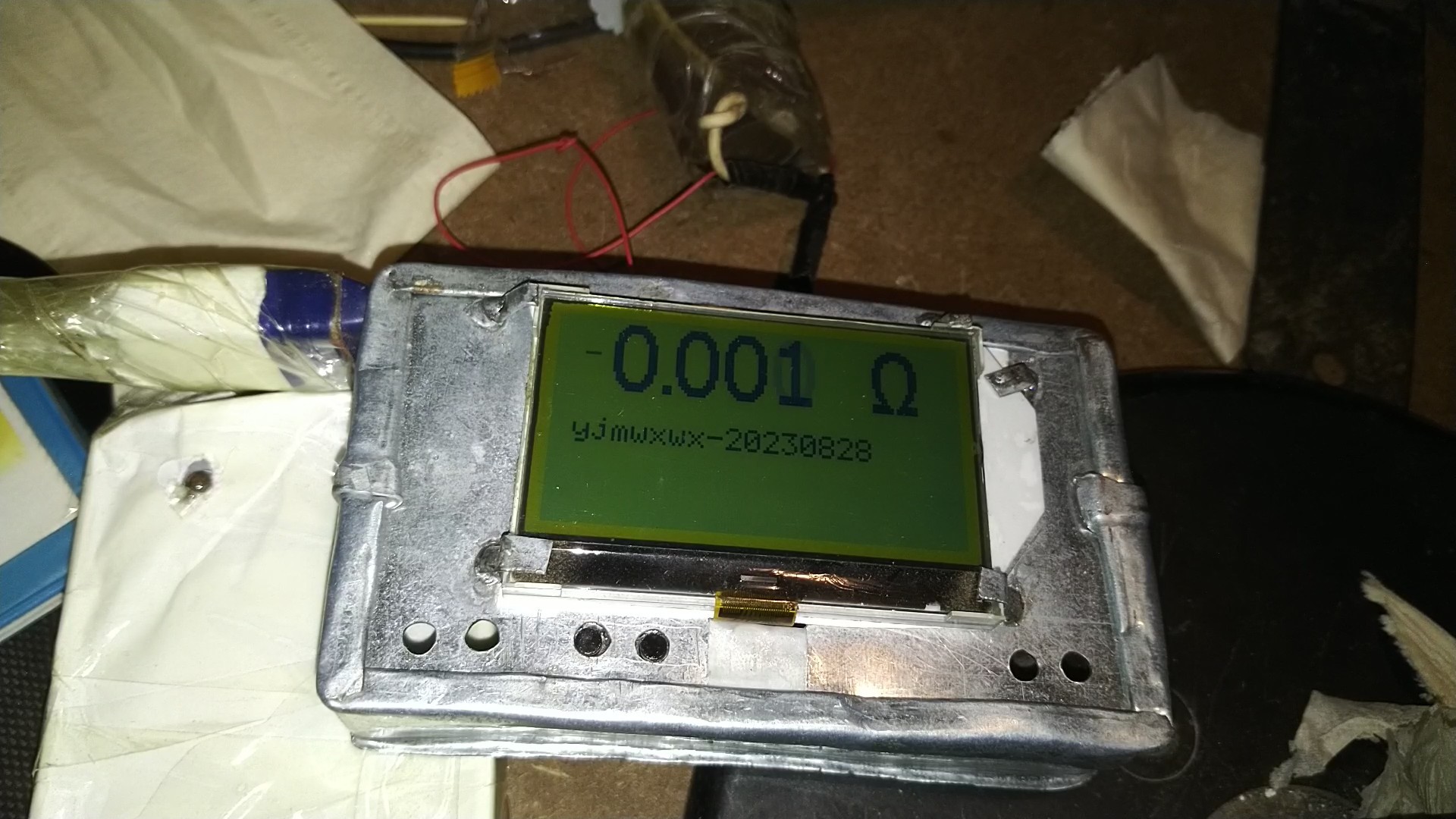
The COG12864 display version is calibrated in the same way as the digital tube display version.
https://www.bilibili.com/video/BV13m4y1T7D8/?spm_id_from=333.999.0.0