 Morning.Star
Started working on the mathematics required for addressing the workspace.
In particular I wanted to look at gears, cogs, bevels, racks and threads which all share the same basic geometry. I wanted to build this into the mill's core to take some of the heat off of gearbox design because up til now, my robotics has been limited to using servos that are expensive and hard to interface to mechanically. I've tried using hobby gearboxes but they are bulky and even more difficult to use, so the only option is to build them myself.
I quickly realised that I'd have to define a paradigm of sorts, or I'd be calculating radii and counting teeth forever just to get two meshes to mate, let alone 4 or 5. The number of teeth and the ratio between the tip and trough seemed to be the most important, so I designed the gear math around this and calculate everything else to match.
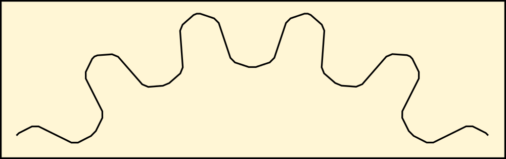
A good mesh is formed by making the bounding box for the tooth square, so the gear is defined as a series of squared segments around a circle, the edges being the centre of the tips.
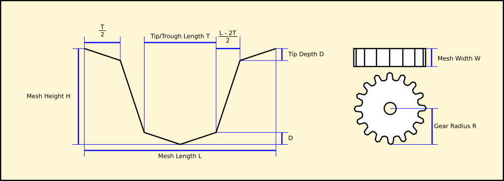
These dimensions are Cartesian and need to be mapped onto a circle for a gear that will mate with a rack of the same dimensions. Each coordinate is taken as an angle and radius from the gear shaft, adjusting the tip width.
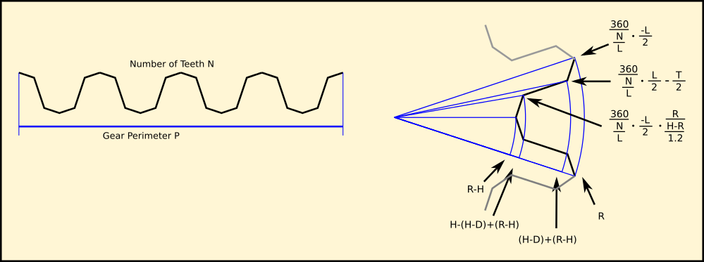
This gives a set of polar coordinates - 360 degrees divided by the number of teeth, divided by the angles formed by the corners. It roughly describes the shape of the mesh but needs work for larger gears to smooth the corners off. I decided to go for a simple chamfer because the maths was already getting a bit hairy...
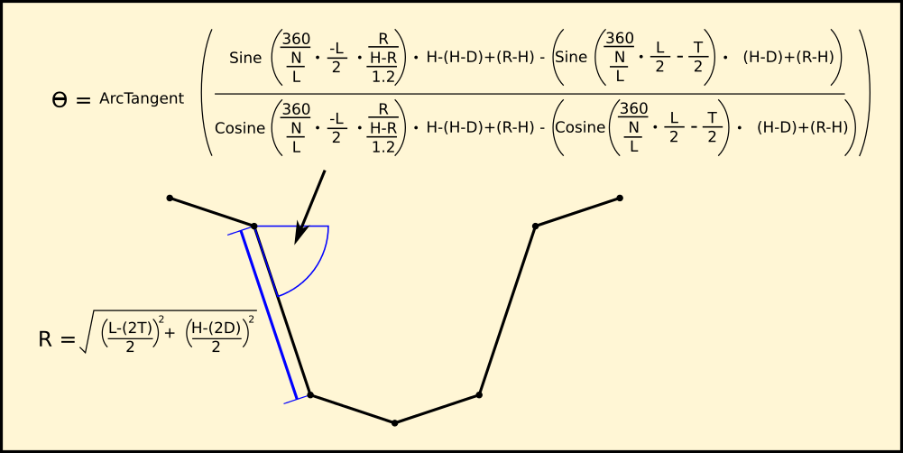
Taking each plane surface in turn, calculate its angle and length. Divide the length by 100 and times it by the required percentage of smoothing...
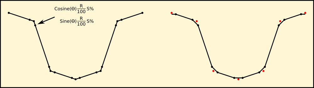
Create a corner either side of the apex, and then remove the apex to leave a fairly smooth tooth profile, providing I keep the tooth size to a sensible maximum. I'm planning on making all my gears match as a set so it is important they are all the same shape regardless of size.
 Sebastian Lenartowicz
 TTN
TTN
 Elliot