 Katsumi
Introduction
Maintaining humidity at home is very important for the health. Too low humidity can cause dryness of the throat, nose, and skin, which can lead to health problems such as an increased susceptibility to colds and nosebleeds. On the other hand, if the humidity is too high, sweating throughout the body does not function well. In addition, mold can easily grow. Therefore, even when using a humidifier, it is important to frequently check the humidity in the room. Typically, it is a good idea to keep humidity at 40-60%.
Commercial humidity monitor is usually not very accurate. It often show humidity with 5-10 % errors. Therefore it is very hard to maintain the humidity in a room within the desired range by using a commercial humidity monitor. On the other hand, the psychrometer is more accurate than commercial humidity monitor and also used for calibration of humidity monitors and humidistats.

The psychrometer is consists of dry- and wet-bulbs of thermometers. Humidity % is calculated from the difference of temperatures of these bulbs. The psychrometer can be constructed with any thermometers, like ethanol-filled glass thermometers (Figure 1). However, to obtain the humidity %, a tedious process is required. 1. Read temperature values of dry- and wet-bulbs. 2. Determine the difference of two values. 3. Use a table to obtain the humidity %.
These tedious steps can be automated by using electric-thermometers and micro-controller. Here I show a project to construct psychrometer with Raspberry Pi Pico, MCP9808, Pico-ePaper-2.13, and 74HC00. After construction of my own DIY psychrometer, I only need to maintain the water in a small container for measuring the accurate humidity in my room.
Components
I chose Microchip MCP9808 as the electric-thermometer. According to Microchip, the typical accuracy is ±0.25 °C and the maximum error is ±0.5 °C. This range of error is acceptable to measure the room temperature. To calculate the humidity, the temperature difference of two chips is important and ±0.5 °C error causes unacceptable error in humidity, but the errors of each chip can be calibrated in advance for accurate humidity determination.
Raspberry Pi Pico is used as the micro-controller for this project. Recently, it is my favorite to construct most electric projects. It is less expensive and has the enough capabilities for my projects. Low power consumption is also good because I prefer battery-powered operation for this type of project.
I chose Waveshare Pico-ePaper-2.13 as the display. The commercial humidity monitors use custom-made LCD for low power consumption, which cannot be applied to DIY project. The ePaper maintains its display even when not powered, so it is a good choice for battery-powered products.
The 74HC00 was used to construct a latch for measuring time by capacitor and resistor. I started the project with this IC in the beginning and am still using it now, but it might be replaced by LMC555 timer in the future.

The sensors and calibration
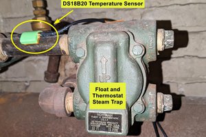
I used two MSOP-8 packages of Microchip MCP9808 as temperature sensors. These have I2C interface, so I assigned 0x1f and 0x1b as I2C addresses for these chips (by coneeting all A0, A1, and A2 pins to Vdd, or connecting A0, A1, and A2 pins to Vdd, Vdd, and GND, respectively). After soldering four wires (Vdd, GND, SDA, and SCL) to the chip, those were encased in epoxy resin (Figure 2).

According to the datasheet, the maximum error of temperature read by this chip is ±0.5 °C, so the maximum error of difference between readings of two sensors is ±1.0 °C. Such error is not acceptable to obtain accurate humidity. Therefore, I calibrated the temperature difference between readings from these two chips.
I don't show the whole source code for measurement, but...
Read more »
 Rohma Khalid
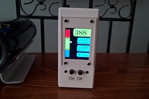
 Arnov Sharma