 Silícios Lab
Introduction
Today I want to tell you what one of the biggest problems is in electronic projects involving the Internet of Things and low energy consumption. In addition to telling you about this problem, we will show you how to avoid it in your projects.
Several electronic projects need to operate with low energy consumption and are powered by batteries. And one of the biggest problems is managing the battery's energy consumption well so that, in some applications, the system works for 1 year, 2 years or more powering your electronic projects.
Therefore, working with batteries can be a big problem if you don't know how to adjust all your circuitry and code to operate at low power consumption and not discharge it quickly. Otherwise, your electronic application will quickly stop working.
After all, how can we monitor our battery's energy parameters and know the ideal time to recharge or change it?
In this article, we will show you how to solve this problem and provide you with the file for an electronic development board based on the ESP32. Through it you will be able to develop countless electronic projects and study energy consumption based on the use of Li-Ion batteries.

Now, let's start the discussion of this electronic circuit.
Circuit Design of the ESP32 Development Board with Battery Voltage Monitory System
Below we have the complete electronic diagram of the printed circuit board project.

As you can see, the project is divided into several electronic blocks and, below, we will explain the main parts for you to understand its complete operation.
ESP32 Circuit
The ESP32 circuit is the heart of this electronic project. This CHIP will be used to process input information and other information that comes from the internet. Below we have the electronic wiring diagram.

As mentioned, many electronic projects need to operate at low power. To power the ESP32, it was necessary to develop a circuit to allow it to be powered by a Li-Ion battery.
However, it is not possible to connect the battery directly to the ESP32, as its voltage is inadequate to be applied to the CHIP.
To do this, it was necessary to develop some circuits to supply a voltage of 3.3V.
See the power supply circuits and the strategy applied for each of them. This made it possible to create a development board that can power countless devices and facilitate the construction of any electronic prototype.
Power Supply Circuit
The circuit power stage was made to meet the following points:
- Provide a stable voltage to power the ESP32 with 3.3V from a Li-Ion battery;
- Provide a voltage of 5V to power other external modules that operate at this voltage.
This way, we will have the flexibility to work with a variety of devices and build countless projects using this development board.
See the 2 main electronic blocks to provide 3.3V and +5V power in the electronic board design.

In the first block we have a step-up circuit. It was designed using the TPS61023 CHIP and is intended to operate with an input voltage range between 2.7V and 4.35V. From this input voltage range, the voltage is raised and it provides a value of 5V at the output of the circuit with a maximum current of 1.5A from a single-cell Li-ion battery. See the complete TPS61023 datasheet and check the application note.
From this voltage, we use an AMS1117 voltage regulator to regulate the voltage and provide a value of 3.3V to power the ESP32 circuit.

The electronic board has several +5V, 3.3V and GND pins. The purpose of these terminals is to facilitate the power connection of other modules and electronic components to have more flexibility when creating electronic prototypes. See the figure above.
And something will happen in your application...
These electronic devices will consume the power of your battery and, little by little, it will discharge. As we have already mentioned, this is a big problem and, therefore, we need to monitor the battery voltage...
Read more »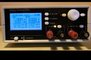
 Manuel Tosone
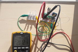

 Joe Miller