 Keith
KeithImage acquisition system
G. J. AWCOCK, F. W. STONE AND R. THOMAS
A low-cost solid-state sensor, coupled with suitable image-processing software, is more than adequate for many applications in robotics, security and character recognition.
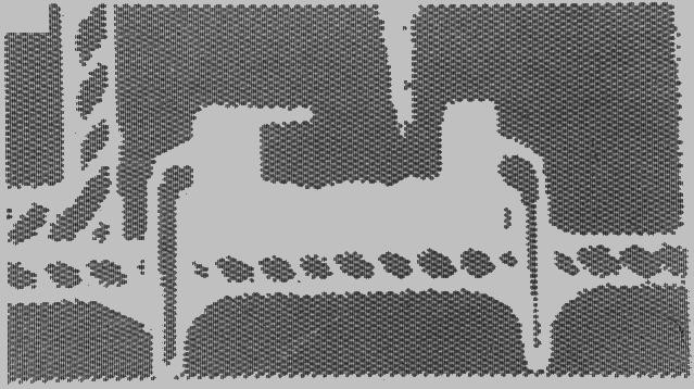 Fig. 1 (above). Raw image acquired by the IS32 sensor: the picture shows light falling on another IS32. |
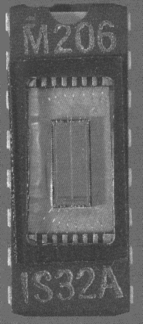 Fig. 2. Micron Technology's IS32 optic DRAM: a 64K memory device with a transparent lid. Price is about £40. |
In many cases the broadcast TV format is selected as the basis of an image processing system for no better reason than its familiarity, or ease of display on standard monitors. However, the quantity of data required to represent a high-resolution image is a major factor contributing to the inaccessibility of computer vision; and so it is essential that very careful consideration of the system requirements should result in a sensor specification which is adequate, and no more.
A conventional TV camera produces an analogue video signal which is continuous in the horizontal axis but discrete in the vertical axis, by virtue of the raster scan method of picture reconstruction. The maximum re-solution in the vertical axis is approximately 574 lines, with interlace, and because the horizontal:vertical aspect ratio of a standard TV screen is 4:3 this implies a horizontal resolution of approximately 765 picture elements (pels, or pixels). Thus the number of pixels required to represent a full-resolution picture is 574 × 765 = 439,110.
If, in addition, each pixel is represented as one of 64 grey levels, i.e. a grey-scale resolution of six bits, the quantity of data which must be acquired for each picture will be a grand total of 2,634,660 bits for a monochrome signal! Thus the scale of the problem of acquiring images and storing them in a personal computer becomes obvious.
In addition, a new picture is generated every 40 ms, leading to a throughput requirement which makes real-time camera/ computer interfaces both complex and costly. This problem has been tackled to some extent for static or slowly changing images by the development of slower multi-frame TV interfaces, which build up their images over a number of consecutive frames. This eliminates the problem of video-rate a-to-d conversion and considerably reduces the cost of an interface, but it does nothing to ease the problem of storing this quantity of data within the computer.
Solid-state image sensors should offer hope of a simpler interface, since the data is inherently discrete in both the horizontal and vertical axes. Generating distortion-free raster scan video is then a relatively simple problem for digital electronics.
Unfortunately, the best known of solid-state sensors, the charge-coupled device (CCD), does not have many advantages over conventional vacuum tube cameras in low-cost applications.
In general, CCDs have been designed with the full TV standard specification in mind, offering spatial resolution of typically 380 × 488 pixels with continuous grey-scale dynamic range of typically 1000:1. Thus they do very little to ease the problem of excessive image data; and a sensor free of blemished photosites (i.e. light-sensitive cells that are defective in some way) costs considerably more than a complete normal TV camera.
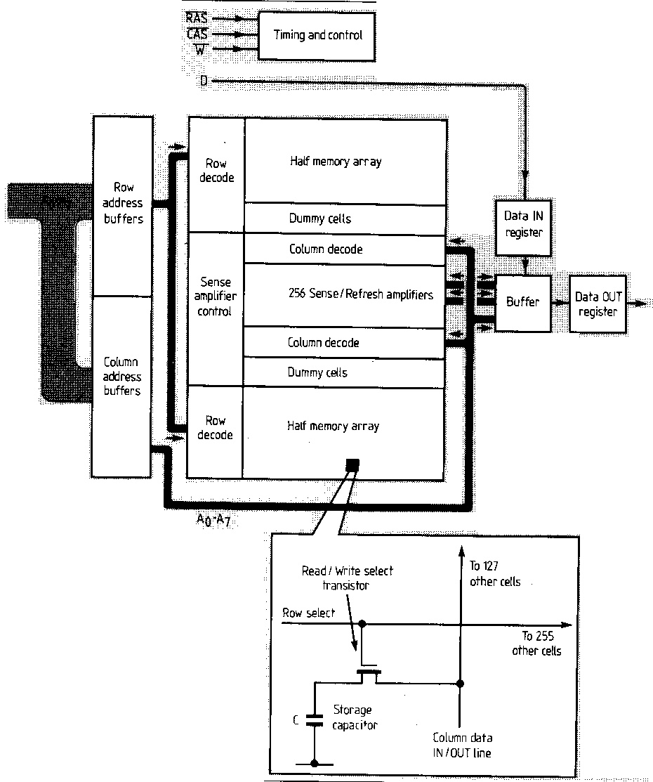
There is, however, a relatively new solid-state image sensor which is ideally suited to experiments with computer vision. The device is the IS32 optic DRAM (Fig. 2) from Micron Technology, which is based upon a 64K dynamic ram and thus offers 65 536 pixels, each having a one-bit grey-scale. The pixels are organised into two banks of 128 × 256, separated by a thin dead-zone, which effectively makes one of the banks redundant for use with normal optical systems. Hence the working resolution of the device is 128 × 256, making it well suited to the high-resolution screen modes of many popular computers. The one-bit grey-scale maps well on to the limited range of colours usually offered in such modes.
The hardware interface to be described here uses only half of one bank of pixels (a 128x128 "quadrant"), because the elongated shape of each pixel (13.6 × 8.8 microns) makes this resolution match the aspect ratio of the computer monitor screen most accurately. Image data from a quadrant may conveniently be stored in 16K-bits (or 2K-bytes).
The binary grey-scale of the system may at first seem a limitation, but it should be remembered that many image processing schemes 'threshold' their grey-scale data at an early stage to produce binary images for their descriptor extraction algorithms to work on.
| Fig. 3. The raw image (top) can be enhanced by software (middle) and processed further (bottom) into a form suitable for character recognition purposes. |  |
However, this system should not be thought of merely as an educational toy, since many applications such as robotics, security and character recognition (Fig. 3.) etc., are perfectly well served by binary images. Indeed, with the careful use of lighting to emphasise the features in the scene, some industrial inspection tasks could be undertaken by systems making use of this sensor. In addition, the small physical size of the IS32 opens up some unique and exciting applications: for example, in the field of robot vision, with the sensor mounted in the end-effector of a robot arm, the so-called eye-in-hand mode of operation*.
*Pugh, A., Second generation robotics and robot vision; Robotic Technology pp. 1-9. Peter Peregrinus Ltd on behalf of the IEE. 1983.
OPERATION OF THE OPTIC DRAM
 |
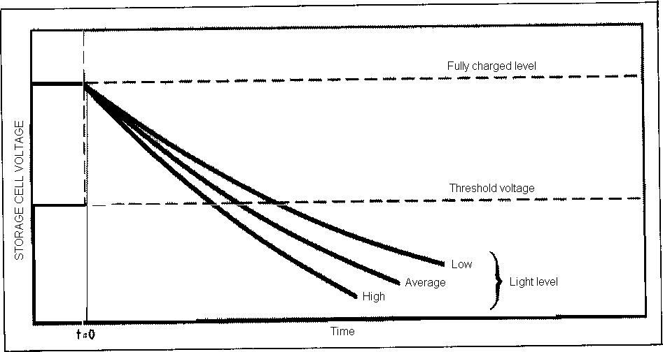 Decay time of the capacitor depends on the incident light level. |
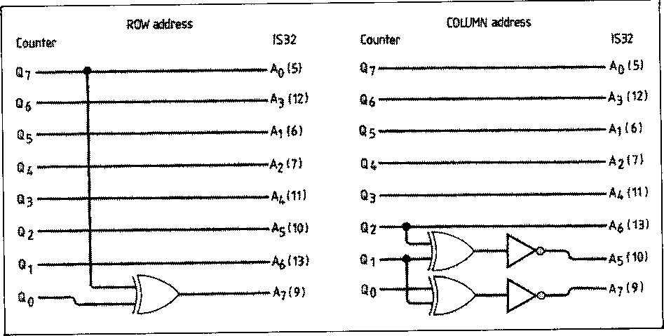 |
 Fig.7. Layout of the IS32 device.
A dead-zone between the upper and lower arrays makes half the device unusable in most optical systems.
Only one quadrant is used in this design; it gives a working resolution of 128×128 picture elements. |
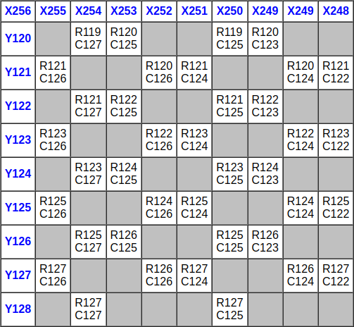 Fig. 7b. This close-up of Quadrant 1 illustrates local scrambling of addresses which remains after the hardware address de-scrambling of Fig.6. Software correction is needed to eliminate it and so linearise the resulting image. Blank cells represent points having no light sensitivity, such as the FET associated with each photosite. |
The mapping that results is shown in Fig. 7(b). Notice that there is still an element of local scrambling and also that only half the surface area of the chip is available for photosites, the rest presumably being occupied by the switching FET that each cell needs. Thus, the second stage involves generating a mapping scheme which has twice the resolution in the column axis to accommodate "space-pixels' which represent the inactive areas of the chip surface, since these must be included for a picture of the correct aspect ratio. Additionally, an algorithm must be applied to sort out the local scrambling evident in Fig. 7, and, furthermore, a slightly different algorithm is required for each of the two cell banks.
In the picture which emerges from this process, 50% of the pixels represent active photosites in the IS32 and can take either black or white states, whilst the remainder are space-pixels which may be displayed in the user's chosen background colour. The use of an enlarged mapping matrix with the inclusion of space-pixels results in subjectively pleasing images with an absence of the annoying "cogging' at straight black/white boundaries that would otherwise be present.
If required, simple picture pre-processing may be carried out to cause the "space-pixels' to agree with the majority of their nearest neighbours.
This type of enhancement will be essential if the image is to be used for further work such as edge detection, and has been applied in Fig. 3 (middle).
| 16384 |
| 256 × 128 grid |
| 2210 × 876.8 microns |
| 6.4 × 6.4 microns |
| 2.52: 1 |
Table 1: characteristics of IS32 quadrant
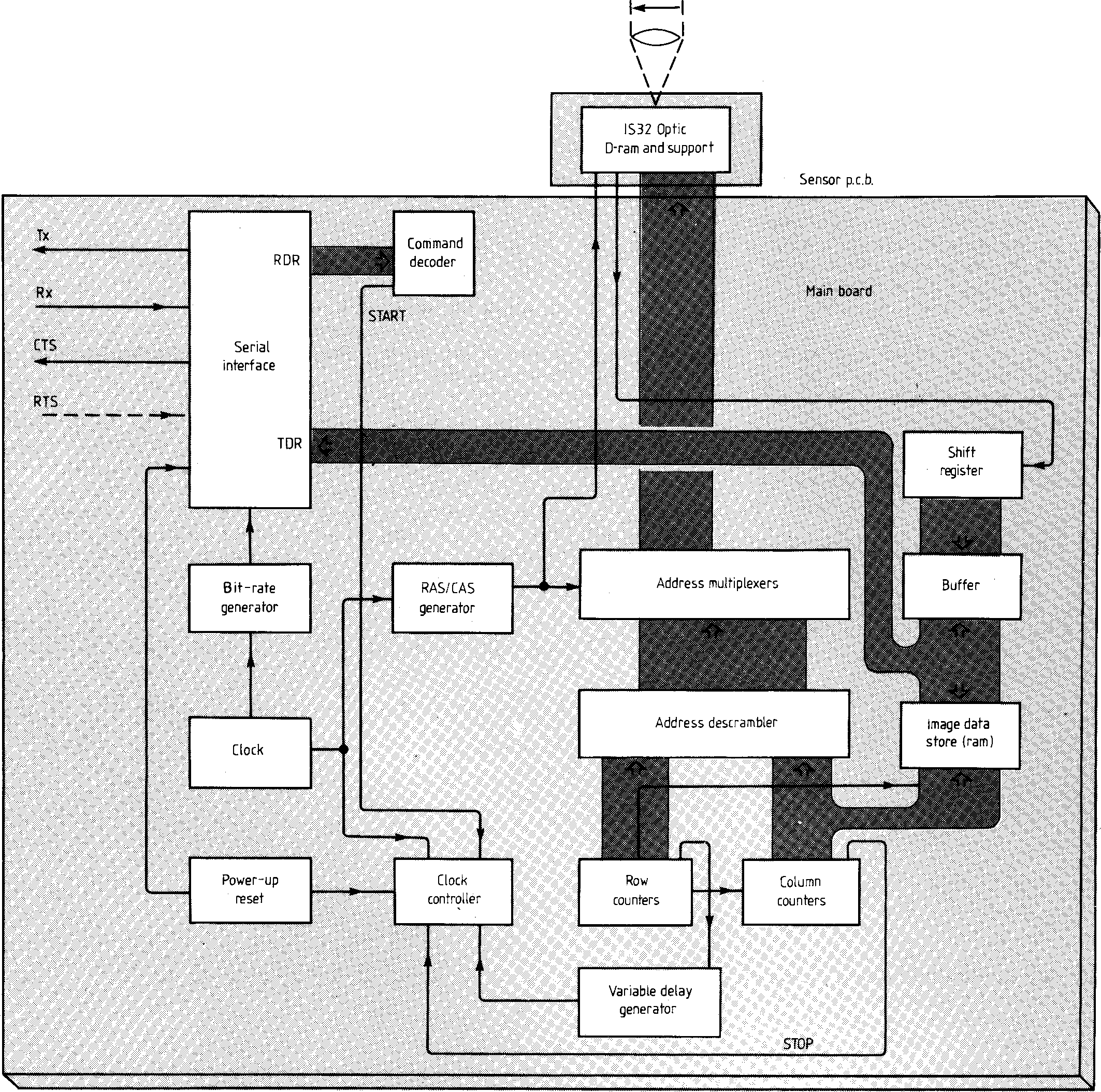 |
IS32 Optic DRAM and support
In the next article, the authors introduce a hardware interface for the IS32 which enables it to be driven via a personal computer over an RS-232 serial link.
Graeme Awcock is a lecturer at Brighton Polytechnic and is reading part-time for a doctorate in computer vision techniques for low-cost robotic systems. Previously he worked as a senior design engineer at Computing Devices, which he joined after graduating from the polytechnic in 1979.
Bill Stone designed the prototype imaging system as his final-year project at Brighton Polytechnic. Since graduating he has been working as a development engineer for MEL at Crawley and is currently involved in the design of electronic support measure systems.
Ray Thomas gained his Ph.D, researching into high-permeability magnetic materials. Subsequently he spent seven years in the electronics industry before joining Brighton Polytechnic as a lecturer in 1977. His interests are in microprocessor applications and computer vision systems.
---
Image acquisition system
Creating software routines for a solid-state computer vision interface
G.J. AWCOCK, F.W. STONE AND R. THOMAS
This image acquisition system is based on a low-cost solid-state sensor device, the IS32 optic d-ram by Micron Technology. The IS32 is very suitable for generating the black-or-white binary images widely used in robotics, computer image processing and character recognition. Hardware for this system is described in the April and May 1987 issues.
The main function of the driver software is to obtain image data from the hardware and then to display it on to the screen of the host computer. A suitable screen mode should be chosen so that the image data can be mapped with an aspect ratio matching that of the sensor. Ideally this should be 1.26:1 to correspond with the effective photosite size of 8.6×6.8μm.
With a BBC computer as host, the best screen modes to use are modes 1 and 4. Mode 4 provides a basic two-colour display whilst using only 10 Kbyte of memory; mode 1 gives the opportunity to add colour to screen messages but requires an extra 10 Kbyte of RAM.
A routine to display a continuously updated image on the computer's screen is shown in Fig.11. First, the initialise procedure sets the computer's serial port characteristics to correspond with the imaging hardware. Sensor quadrant selection is performed by transmitting codes to set or reset the row and column address m.s.bs (Table 2 last month). Finally, control passes to a loop which performs the continuous updating; it starts by transmitting the code to initiate the scan macro-task in the hardware.
It is desirable to employ a display-whilst- scan technique, since this introduces a degree of parallelism which shortens the image update loop as the computer need not wait for the sensor to finish capturing an image. This means that as soon as the sensor scan has been initiated the host begins to plot image data resulting from the previous scan, whilst the hardware is performing its dedicated task.
In the case of the first traverse of this loop after initialisation, the resulting image will be quite meaningless, being a display of random memory contents. Also, the displayed image will always be one step behind the image currently being captured by the hard- ware. But whilst this can be momentarily confusing, it should not present any serious drawbacks in the majority of applications.
On completion of a scan or of the display process, whichever takes the longer, the code to start the read macro-task is transmitted to trigger the transfer of image data from the most recent sensor scan back to the host. When the raw (i.e. packed and partially linearised) image data is received, it is better to buffer it in the computer's main memory, rather than to attempt to de-scramble it fully and plot it directly on the screen. This allows fast hardware-to-host transfer rates to be achieved. The prototype system was run at 19200 baud with no serial link handshaking, using a BBC computer as host.
To enable the update loop to be terminated, a keyboard scan routine should be included at a suitable point in the cycle. This would allow an interesting image to be frozen by pressing a key and saved to disc for subsequent processing or enhancement.
IMAGE DATA DISPLAY
Plotting the buffered image onto the screen is the most complex task of the image update software. Details of the algorithm will vary for different host machines because of their particular graphic screen memory allocation. Thus, in developing a suitable algorithm for the display task the major factors to be considered are
- the screen memory map of the host: the need for speed prohibits the use of operating system calls which would otherwise allow plotting by means of standard X and Y graphics coordinates.
- the relationship between the orientations of the sensor, the scene and the computer screen, taking account of inversions caused by the optical system employed.
Optical arrangements in the prototype consisted of a modified photographic enlarger with the sensor surface in the film plane. Subject matter could be placed on the baseboard and the image focused on to the front face of the sensor with the normal bellows focusing control and the enlarger head's height control. Since the front face of the sensor is the surface pointing away from the observer, the display automatically compensates for the lateral inversion inherent in the optics. However, optical inversion in the vertical direction must still be corrected and this dictates that the sensor pixels along the X-axis (or rows) should be plotted in reverse order on the screen for a correctly oriented image.

Fig.11. Basic image update routine.
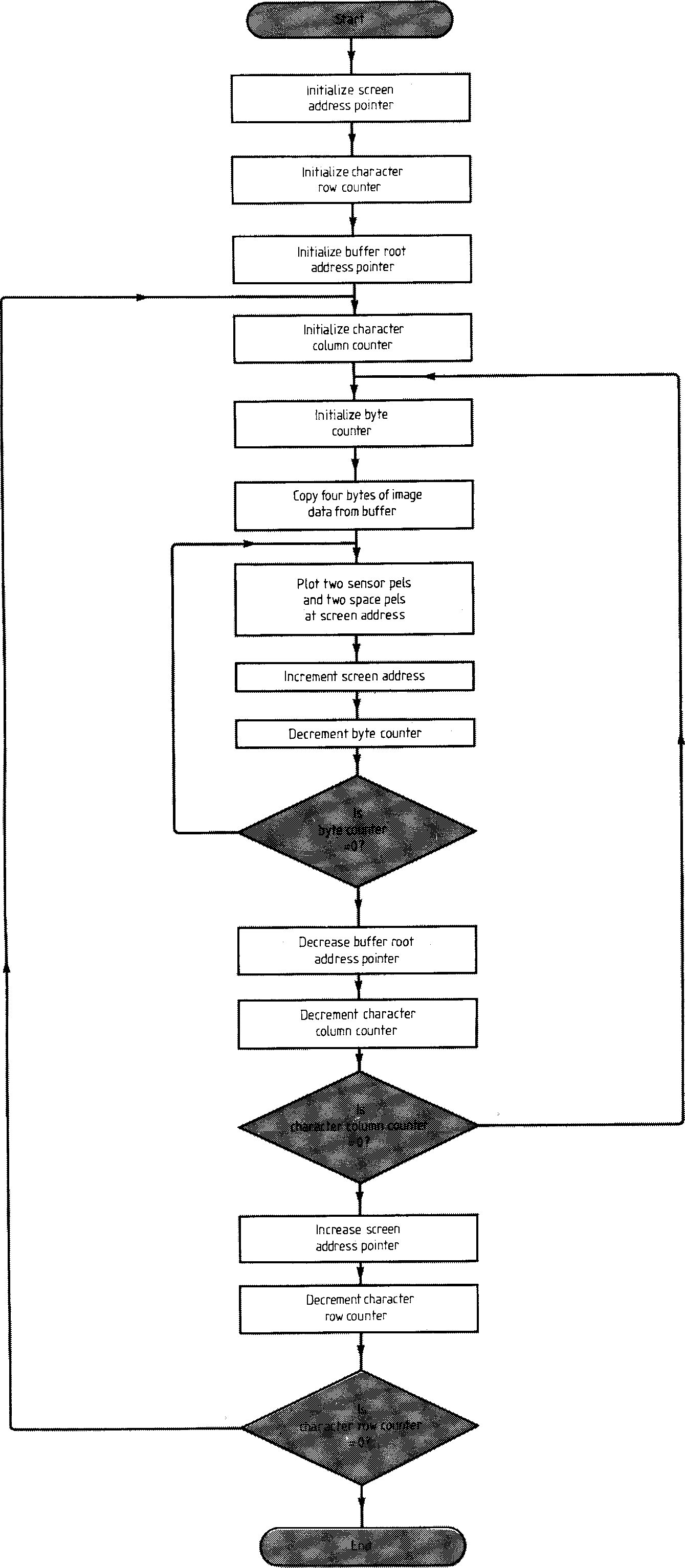
Fig.12. Image display routine for the BBC Micro in mode 1. In this machine screen memory is organised into character-sized cells, a factor which must be taken into account in plotting graphics.
Figure 12 shows an image display routine for mode 1 graphics on the BBC micro, and is inevitably partially specific to that machine. However, it should serve to illustrate the principles of writing software for other computers.
The screen of the BBC micro is controlled by a 6845, which is a textual or 'character'-oriented c.r.t. controller. In effect, it organises the screen into 'character' rows and 'character' columns, each character cell using eight consecutive bytes of memory (regardless of graphics mode). In mode 1 the screen is divided into 32 rows of characters, each containing 80 four-pixel-wide character columns; each character cell is four pixels wide by eight deep. It is necessary to employ an area of screen memory corresponding to 64×16 characters to plot an image of 256x128 pixels. Therefore the image plotting routine basically consists of three nested loops, one to count the number of bytes in a character cell, and two more to count the character rows and columns respectively. Each counter should be linearly incremented or decremented to achieve the speediest method of driving the inner loop algorithm around the image plotting area.
The inner loop is repeated eight times under the control of the byte counter, and is responsible for the plotting of two active pixels (plus two space pixels) in each of the eight consecutive screen addresses comprising a character cell. The middle loop is under the control of the character column counter which causes the inner loop to be repeated 64 times, thereby plotting eight screen lines, each containing 128 active pixels and 128 space pixels; i.e. a character row. The final, outer, loop is thus controlled by the character row counter and allows 16 character rows of data to be plotted down the screen, yielding a total of 128 screen lines as required. Thus the final image matrix consists of 128 lines each of 256 pixels, making a total of 32 768 pixels; but it must be remembered that half of these are space pixels not supplied by the sensor.
INNER LOOP ALGORITHM
Consideration of the method used by the hardware to pack the data into bytes will reveal that the position of any data bit, indexed by (IS32 column, IS32 row) in the memory buffer may be found by applying the following equations:
Byte address buffer root address + column 16+ (row DIV B) (1)
Bit number = 7-(row MOD 8) (2)
These equations assume that the received image data stream is stored in consecutive bytes from the buffer root address upwards. They return the address in the buffer of the byte containing the desired bit and its bit. number within that byte. If, for example, the buffer root address was &2800, then the sensor pels contained at the top of this data table would be as shown in Fig.13.
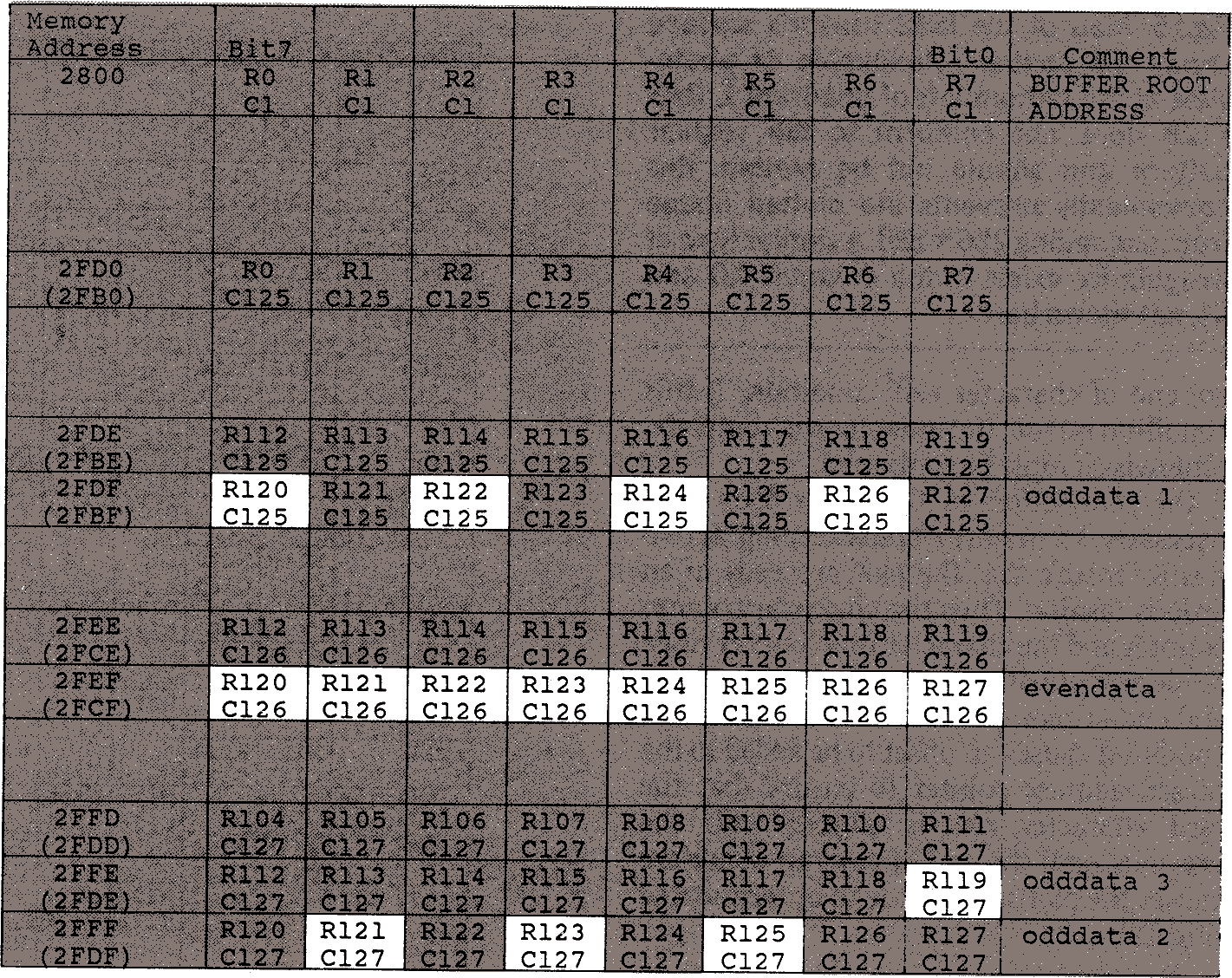
Fig.13. Buffer memory contents. R and C denote row and column addresses of the IS32 sensor. Highlighted boxes hold sensor data to be plotted at the extreme top left of the display (Fig.14). Figures in brackets are buffer addresses for the next character cell on the current character row. When one of these addresses is in force, IS32 column numbers must be reduced by 2; and so the last line in the table becomes-
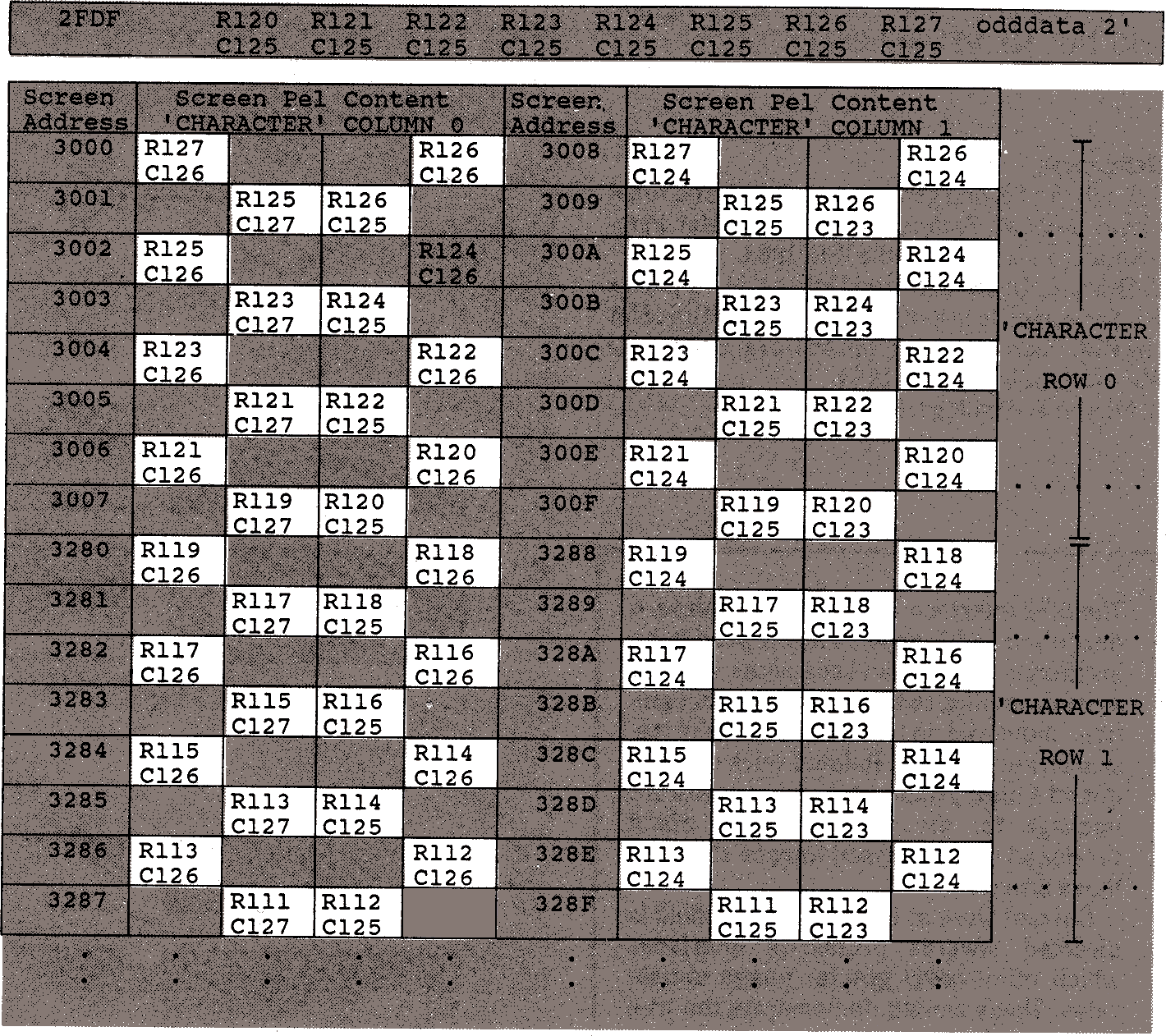
Fig. 14. Top left-hand corner of the displayed image shows BBC mode 1 screen addresses.
With the BBC computer in mode 1, each pixel can take one of four colours. A screen byte contains only four pixels and in this application two of these will be used to represent active photo-sites whilst the other two will represent space pixels and must be left at the chosen background colour. Figure 14 assumes that the image is to be displayed in the top left corner of the screen (screen address pointer initialised to &3000), and shows the relationship between screen memory addresses and IS32 sensor pixels required for the first few character cells.
Figure 15 is an enlarged map of the bottom left corner of quadrant 1 on the sensor's 'upper' array (Fig.7, April issue, page 443). This region of the quadrant will be plotted in the top left corner of the screen to compensate for the vertical inversion discussed earlier and so it contains the data to be plotted in the screen memory addresses shown in Fig 14. Highlighted boxes in Fig.13 show where the corresponding pel data is stored in the buffer. Thus for each set of eight consecutive screen addresses, pel data from four widely separated bytes in the buffer is needed. Data highlighted in Fig. 13, 14, 15 reveals a repeating pattern which generates the algorithm for the second stage linearization process, which may be applied to the inner loop of Fig.12.
Before entry to the inner loop, the image data byte pattern containing pixels that must be plotted into the character cell will have to be copied from the buffer. This is facilitated by setting up a buffer base-address pointer to locate the bytes that will be used. This pointer is initialised to an address near the top of the buffer, which is where the first data to be plotted may be found. At the end of each pass of the inner loop the pointer is moved to locate the next set of data.
Figure 14 shows that moving from a pixel in one character cell to the corresponding pixel in the adjacent cell on the same character row requires that the IS32 row numbers remain constant, whilst IS32 column numbers are decremented by two. Similarly, moving from a pixel in one character cell to the corresponding pixel in the adjacent cell in the same character column requires that the IS32 column numbers remain constant, whilst row numbers are decremented by eight. Using equations 1 and 2 we can deduce the two fixed decrements which are required to move the buffer base-address pointer as the character cell currently being plotted is moved around the screen in increments of one character position. Thus, in the prototype software, a pointer decrement of 32 bytes is required to move one character to the right, whilst a decrement of 1 byte is required to move one character down the
screen.
The second-stage linearisation algorithm is centred on the inner loop, which is responsible for plotting the sensor data into character cells under control of the byte counter. The byte counter holds the three least significant bits of the screen memory address and thus determines which line of the current character cell receives data. Sensor data to be plotted on even lines of the character cell is contained within one buffer byte (labelled Evendata in Fig.13), whilst data to be plotted on the odd lines is distributed amongst the other three relevant buffer bytes (labelled Odddata1-3 in Fig.13). It is also necessary to determine which two of the four pixels described by each screen memory byte receive the photosite data; and this can be achieved by testing the byte counter to see whether it is odd or even. If the counter is even, image data will be found in Evendata and must be mapped into the outer pair of the four pixels from a screen memory byte; otherwise, the data will be located in Odddata1-3 and the inner pair of pixels must be plotted (Fig.14). This algorithm is summarised by the flowchart of Fig.16 which also indicates the way in which data bits may be extracted from their buffer bytes by right rotation of each byte prior to plotting.
Note that this algorithm assumes that the whole screen has previously been cleared to background colour: this improves speed by removing the necessity to plot the space pixels individually.
When the screen memory byte has been written according to the algorithm, the screen address pointer (which was initialised to &3000) is incremented, and the byte counter must be decremented and tested for an 'end of character cell' condition. If this condition is true, the inner loop is complete; otherwise it must be continued.
On completion of the inner loop it is necessary to perform housekeeping activities to ensure that the plot proceeds in an orderly fashion. Thus the character column counter and the character row counter must be decremented and tested for end-of-row and end-of-plot respectively. The end of row condition causes an offset to be added to the screen address pointer to ensure that the next character row is aligned with the previous one; the end of column condition causes the plotting routine to be terminated (Fig.12).
An enhanced version of the software described in this article is available on disc for the BBC Microcomputer at £7.50 including postage and the cost of the disc, from Bill Stone, 77 St Sampson Road, Broadfield, Crawley, West Sussex RH11 9RP. Please specify either 40 or 80 track disc. The IS32 sensor is distributed by Joseph Electronics, 2 The Square, Broad Street, Birmingham, B15 1AP, tel. 021-643 2011.
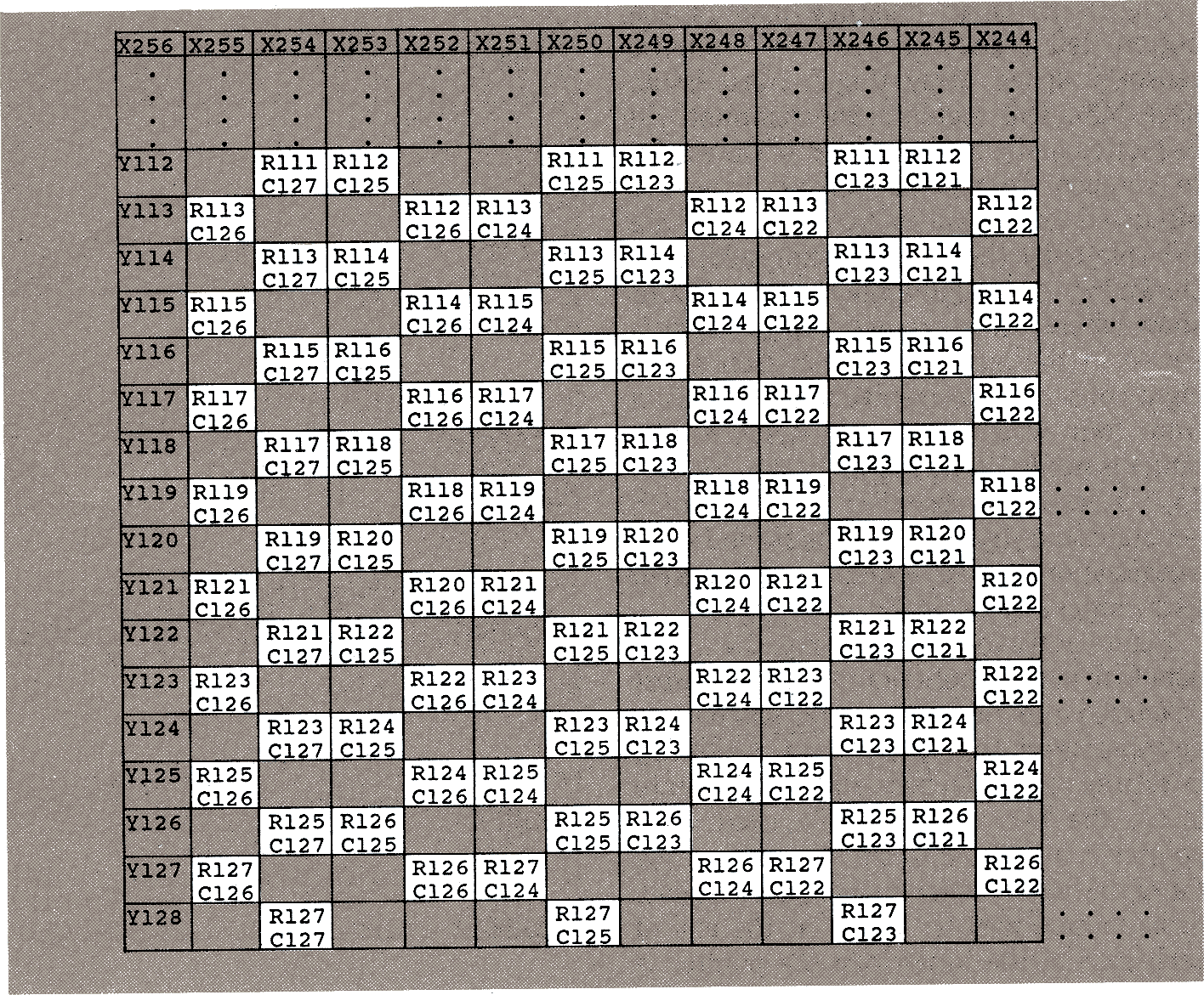
Fig.15. Map of the IS32 sensor's surface shows the spatial relationship of photo-sites at the bottom left of quadrant 1.
Row Y128 does not conform to the regular pattern and should not be plotted: this conveniently prevents the plotted image from exceeding 256 × 128.
A similar type of irregularity exists in the columns X0 and X1, not shown here.
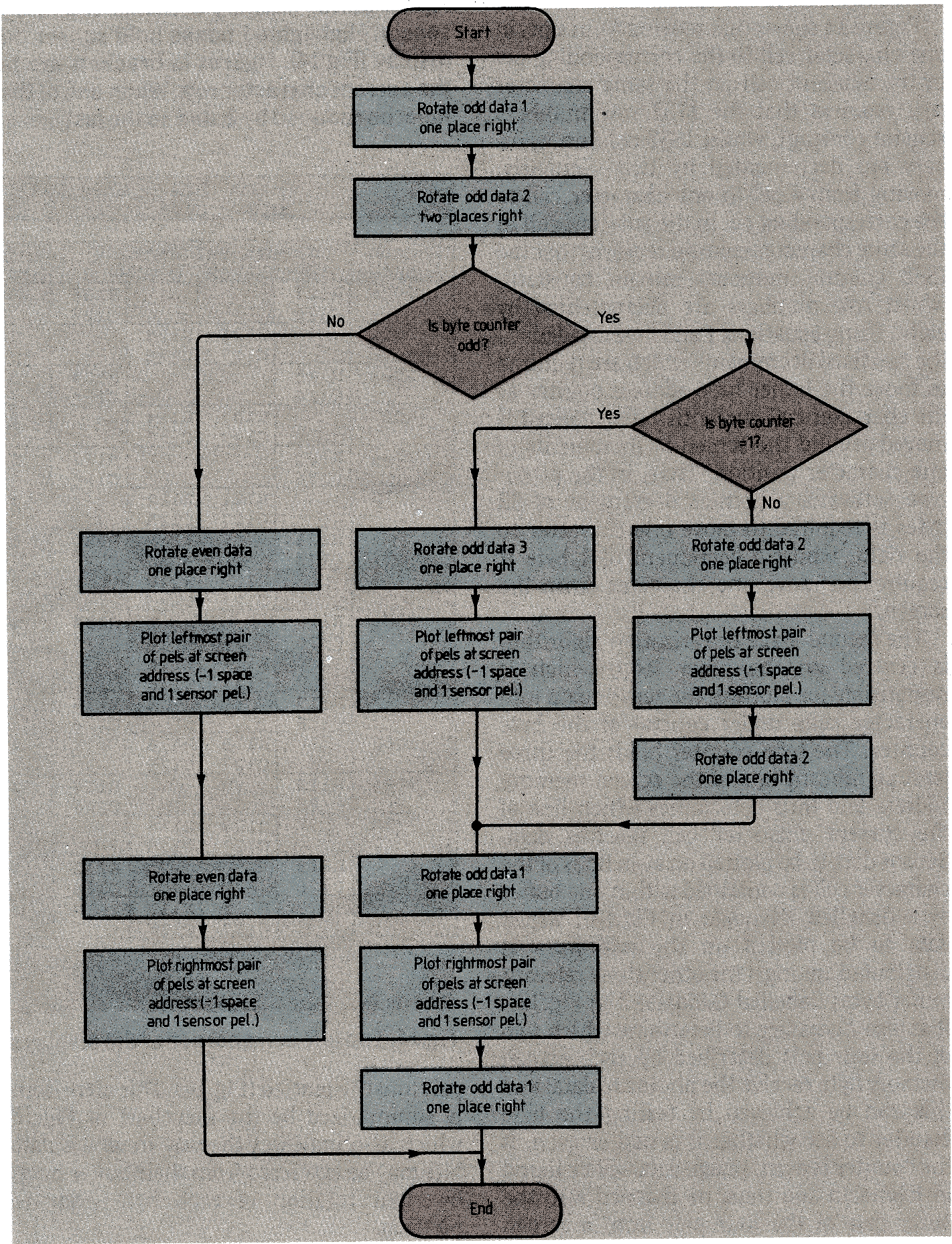
Fig.16. This inner loop flow-chart routine assumes that the screen has previously been cleared to background colour.
References
- Pugh, A.; Second generation robotics and robot vision:
Robotic Technology, pp. 1-9, Peter Peregrinus Ltd., on behalf of the IEE, 1983. - Bray, A., Dickens, A. and Holmes, M. Appendix F-Screen mode layouts;
Advanced User Guide for the BBC Microcomputer, pp. 462-471, Cambridge Microcomputer Centre, 1983. - Micron Technology: IS32 data sheet.
The IS32 interface hardware and software described in this article have proved to be invaluable tools in investigations into image processing, optical character recognition, industrial inspection and other research applications. Related work has produced a binary image processing software package for the BBC computer which produced the processed images shown in these articles.
Current work at Brighton Polytechnic is directed towards producing interfaces which offer vastly greater image update rates. These should demonstrate the true potential of this versatile image sensor in the field of robotic visual feedback. However, the present system is perfectly adequate to allow investigations into the feasibility of such applications, since it allows the cheapness, small physical size and, more fundamentally, the minimised computational expense, offered by the IS32 to be exploited in multiple viewpoint and/or 'eye-in-hand' modes of operation.
Discussions
Become a Hackaday.io Member
Create an account to leave a comment. Already have an account? Log In.