gokux
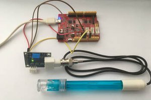
gokuxIn this project, we will create a simple project that imitates the movement of a flexible sensor with a servo. It is an excellent project for beginners to learn about servos and flexible sensors.
Supplies
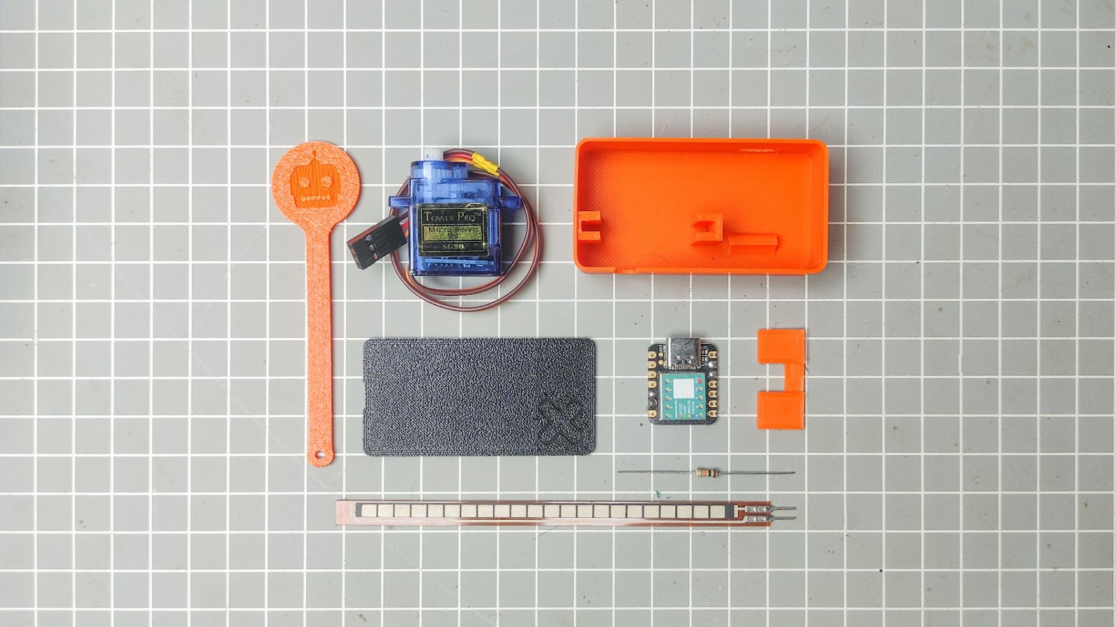
Parts
Tools
- Glue gun
- Soldering iron
- 3d printer
- soldering kit
- small gauge wire
- Wire stripper
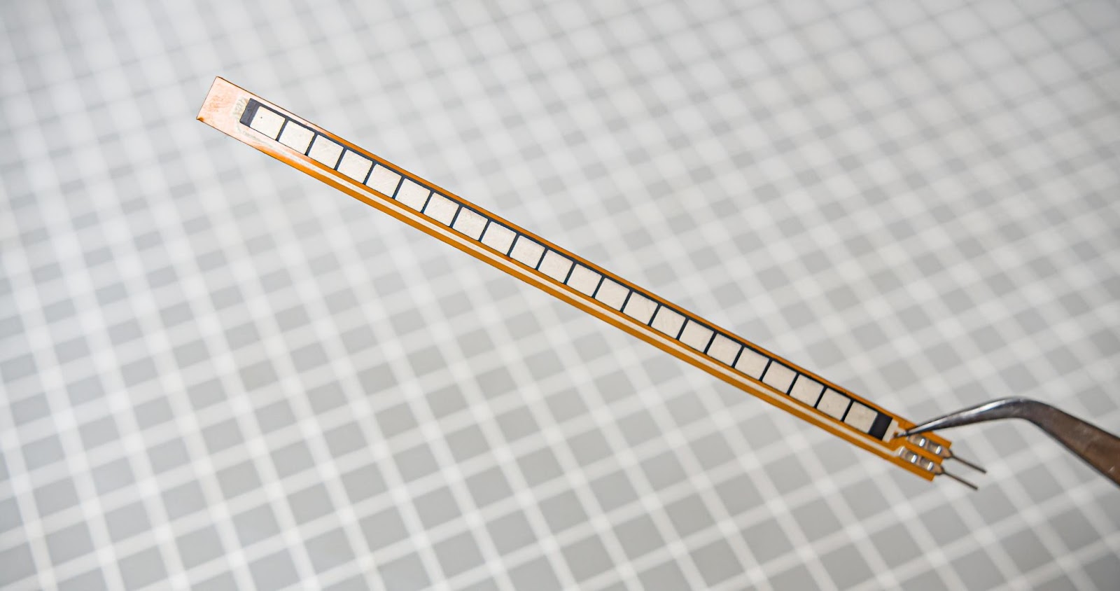
how the flux sensor works
Flex sensors, also known as bend sensors, measure the degree of bending or deflection in an object. They operate by altering the sensor element's resistance when the surface is bent, with the resistance being directly proportional to the amount of bend.
Modelling in Autodesk Fusion 360 and 3D Printing
My project was planned and designed using Fusion 360. The main body is designed to hold all of the electronics and servo motors. This device is powered by USB. All design files are attached below.
Uploading Code To XIAO
I always like to upload the code to the microcontroller before assembly. Here we are using a tiny Xiao SAMD21 from the Seeedstudio
If you need to learn more about Xiao SAMD21 here is a use full video
Seeeduino XIAO - 32-bit Arduino-compatible Microcontroller
CODE
// Include the servo library to add servo-control functions:
#include <Servo.h>
// Create a servo "object", called servo1. Each servo object
// controls one servo (you can have a maximum of 12):
Servo servo1;
// Define the analog input pin to measure flex sensor position:
const int flexpin = 0;

void setup()
{
  // Use the serial monitor window to help debug our sketch:
   Serial.begin(9600);
  // Enable control of a servo on pin 9:
  servo1.attach(9);
}
void loop()
{
  int flexposition;    // Input value from the analog pin.
  int servoposition;   // Output value to the servo.


  // Read the position of the flex sensor (0 to 1023):


  flexposition = analogRead(flexpin);


  // Because the voltage divider circuit only returns a portion
  // of the 0-1023 range of analogRead(), we'll map() that range
  // to the servo's range of 0 to 180 degrees. The flex sensors
  // we use are usually in the 600-900 range:


  servoposition = map(flexposition, 600, 900, 90, 0);
  servoposition = constrain(servoposition, 0, 90);


  // Now we'll command the servo to move to that position:


  servo1.write(servoposition);


  // Because every flex sensor has a slightly different resistance,
  // the 600-900 range may not exactly cover the flex sensor's
  // output. To help tune our program, we'll use the serial port to
  // print out our values to the serial monitor window:


  Serial.print("sensor: ");
  Serial.print(flexposition);
  Serial.print("  servo: ");
  Serial.println(servoposition);


  // Note that all of the above lines are "print" except for the
  // last line which is "println". This puts everything on the
  // same line, then sends a final carriage return to move to
  // the next line.


  // After you upload the sketch, turn on the serial monitor
  // (the magnifying-glass icon to the right of the icon bar).
  // You'll be able to see the sensor values. Bend the flex sensor
  // and note its minimum and maximum values. If you replace the
  // 600 and 900 in the map() function above, you'll exactly match
  // the flex sensor's range with the servo's range.


  delay(20);  // wait 20ms between servo updates
}
Wiring Diagram
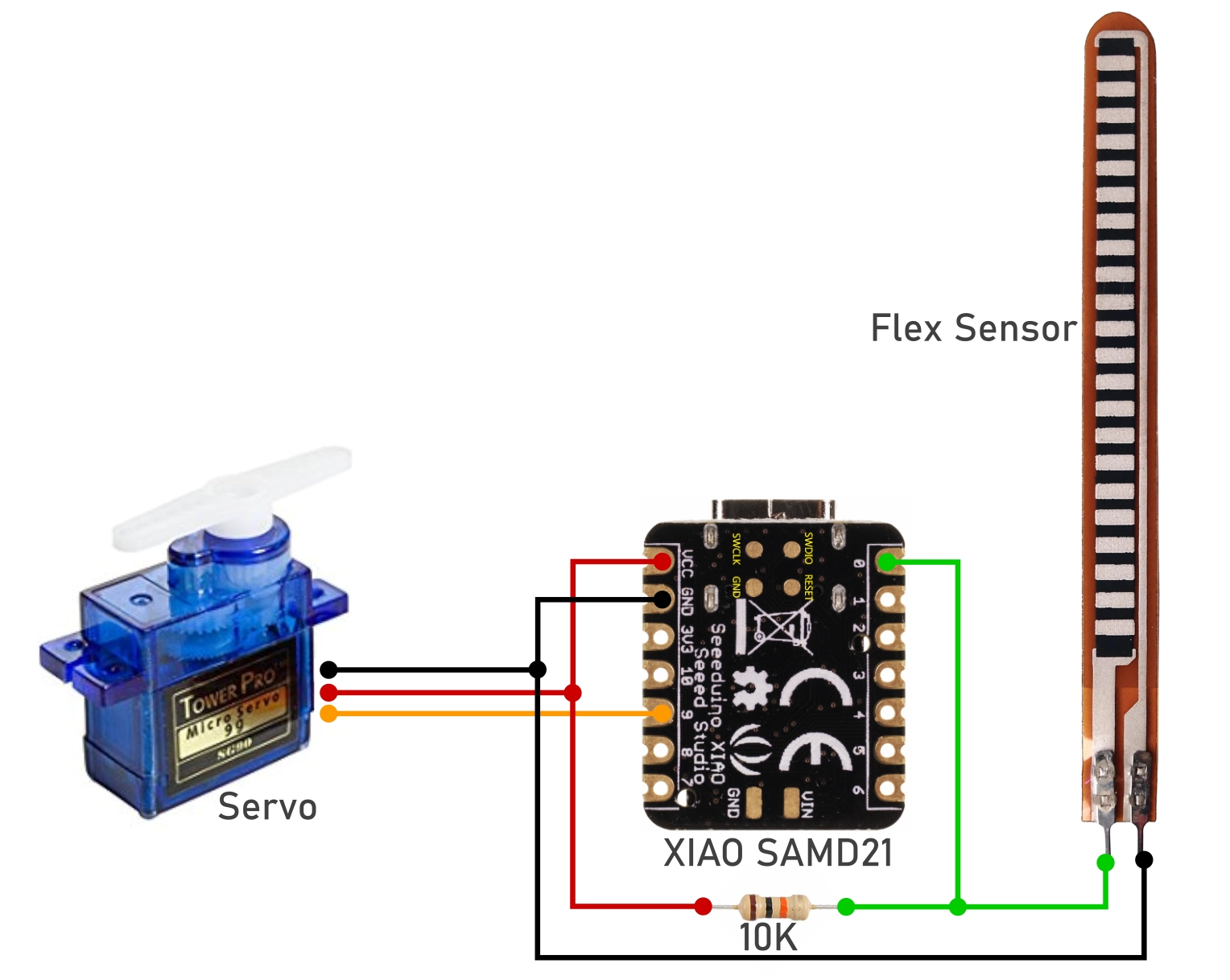
Assembly And Wiring
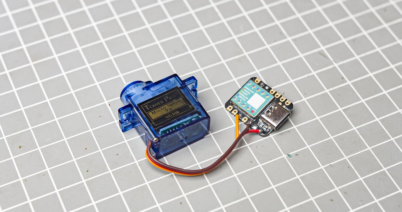
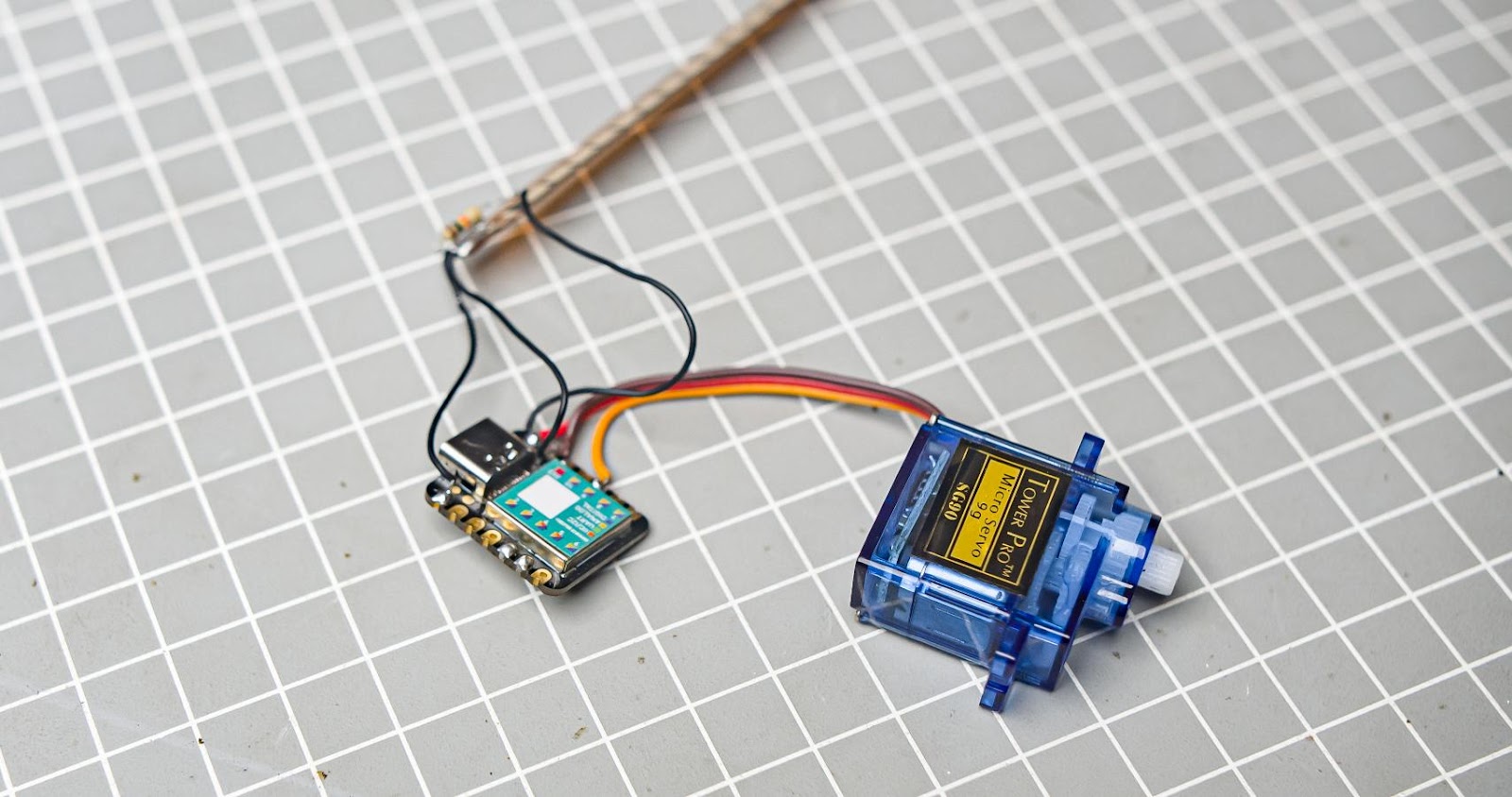
Step 5.1
We need to cut the servo wires to the appropriate length. Then, proceed to solder the wires into the Xiao microcontroller.
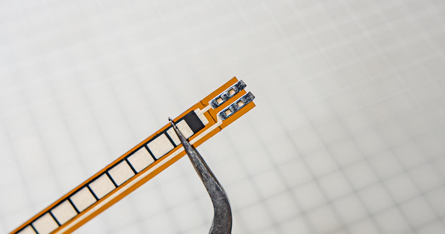
Step 5.2
Please cut the soldering terminals of the flex sensor.
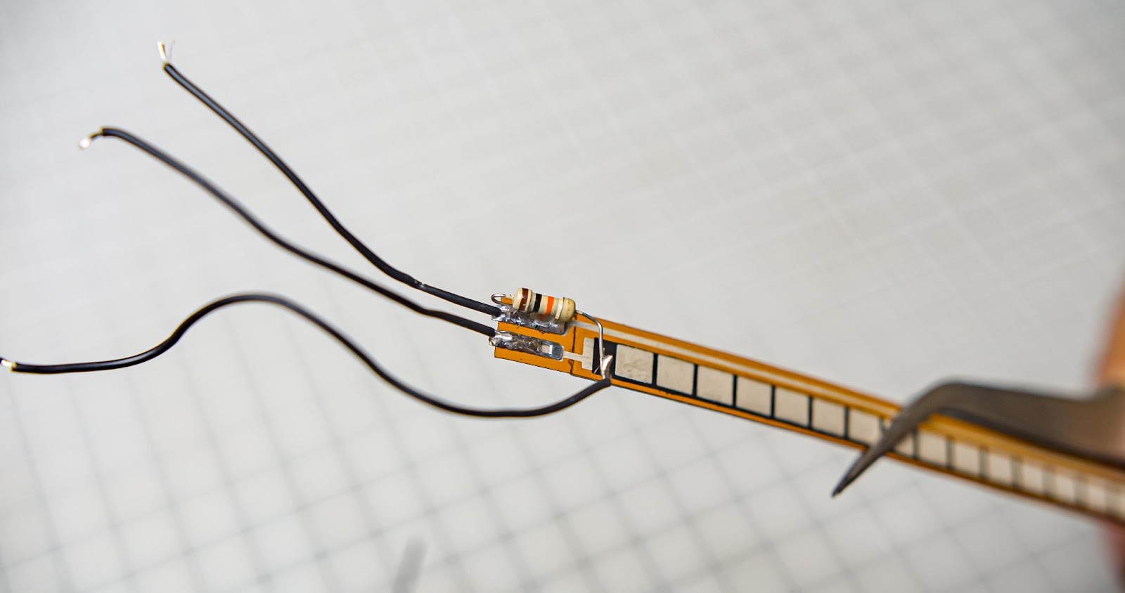
Step 5.3
Solder 10k resistor into the flex terminal and bend it to 180 degrees.Solder rest of the wires from the flex sensor
Step 5.4
Shoulder all the wires from the flex sensor into the Xiao
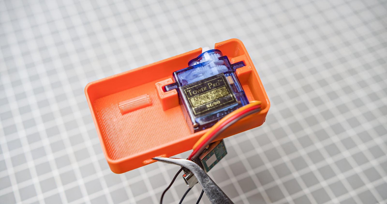
Step 5.5
Put the server into the 3d printed slot
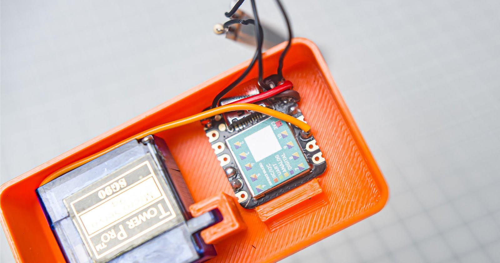
Step 5.6
Push the into the 3D print. Also, make sure to align the USB-C port. Xiao will snap in place
Step...
Read more »

 txdo.msk
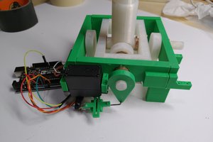
 Matt Dombroski