 mircemk
By calculating the time difference between sending and receiving the sound wave, the distance to the object can be determined using the speed of sound in air. In some of my previous videos, you can see several different builds of such a device with special functionalities. All of them display the result on a PC monitor using an additional program written in the Processing application. This time I will describe to you a simple way how to make an independent Sonar, where the results are displayed on a TFT color display in the form of a radar image, which is why it is often mistakenly called radar instead of sonar.
I got the idea quite by accident from a picture on the internet, and then after a little research I found that project on Github. The original project was made on a 1.8 inch display which is really a very small surface for this purpose. So I reworked the code for a larger 3.2 inch TFT display, where the image is much clearer.
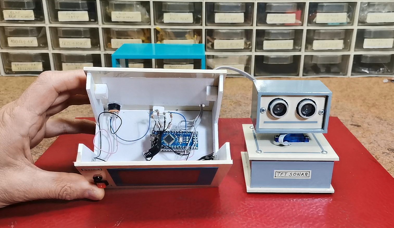
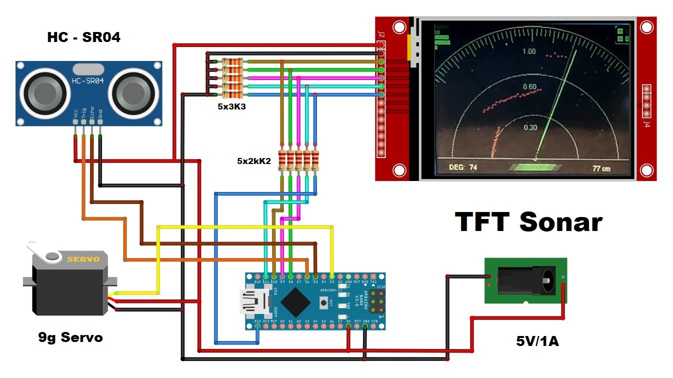
The device is really simple to make and consists of only a few components
- Arduino Nano microcontroller board
- TFT display with a resolution of 240 x 320 pixels and an ILI9341 driver chip
- Ultrasonic sensor type HC-SR04
- small 9G Servo
- and several resistors that serve to shift the display signal from 5V to 3.3V level
The servo and ultrasonic sensor are housed in a separate box, which I used from a previous project, and connected to the main box with flat cables.
Now let's see how the device works in real conditions:
At the beginning, I separated the ultrasonic sensor from the servo in order to calibrate the graphic presentation with the real distance of the object. As you can see, the real distance fully corresponds to the distance shown on the display.
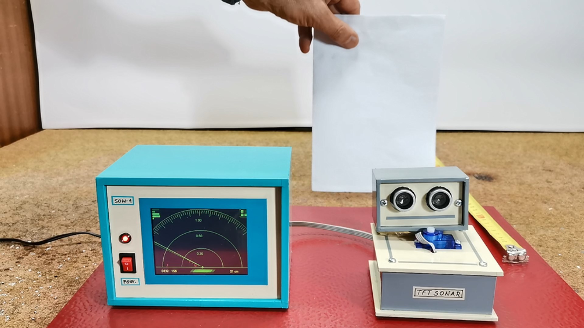
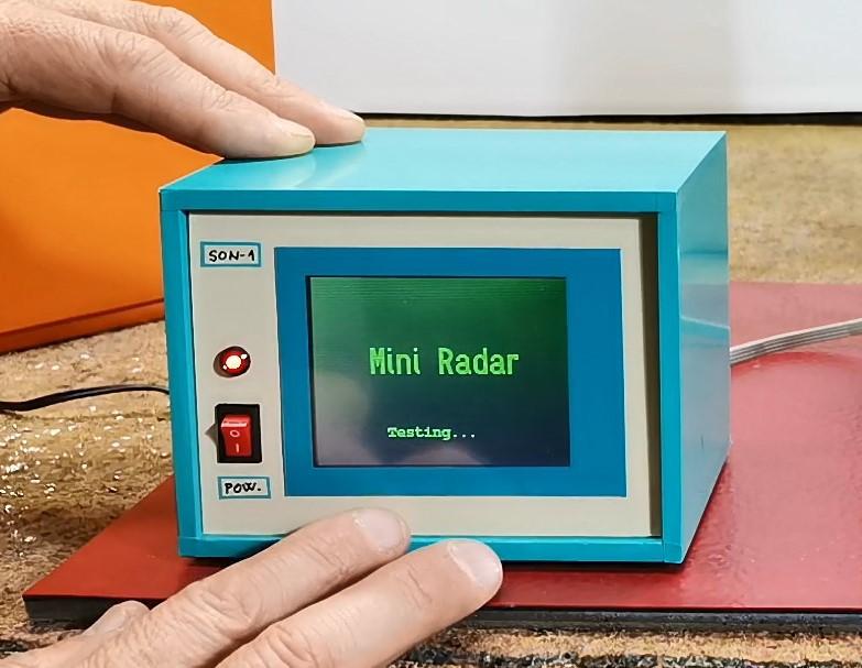
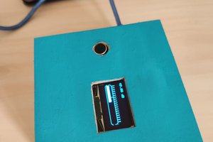
Now we mount the sensor on the servo and place the obstacles to be detected. At power on, the servo is tested first, then the Radar like screen is drawn on the display and scanning begins.
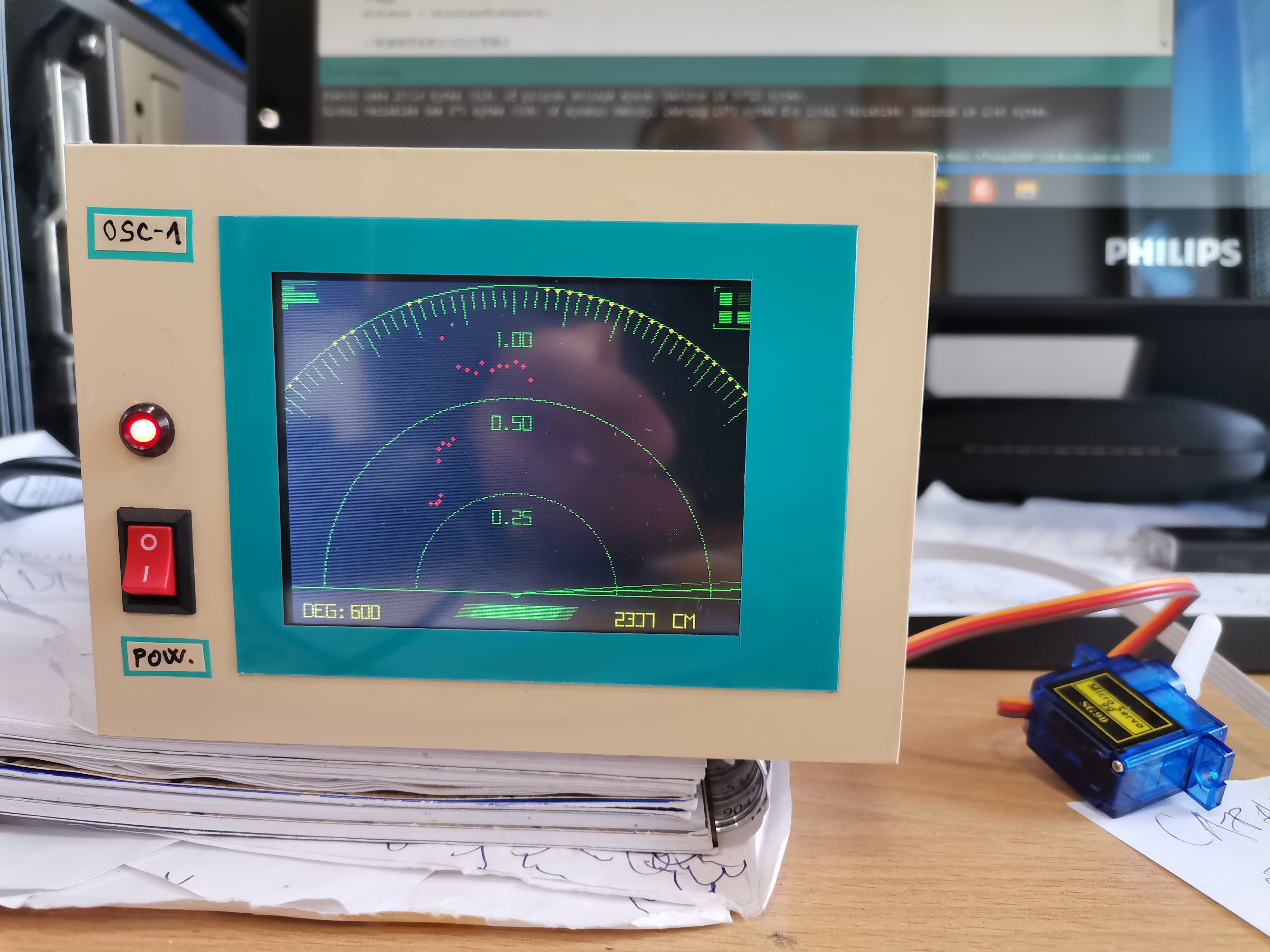
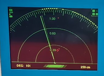
Obstacles are marked with red dots. In the lower left corner, the scanning area is displayed, and on the right, the distance between the sensor and the obstacle in centimeters. The three green arcs with marked distances serve us for easier visibility and an idea of the real distance. If the nearest obstacle is greater than 1 meter, yellow dots are drawn on the last arc, indicating an out of range condition. Scanning is performed first from 180 to 0 degrees, and then vice versa, from 0 to 180 degrees.
For the sake of stability during operation, the device is preferably powered by an external power source, but it also works via USB on the Arduino. All display colors can be easily changed in the code according to the user's preference.
And finally a short conclusion. Most such devices show the scan result on a PC monitor which requires an additional application and code. This is a very simple, easy to make, visually effective, and self-contained device intended for both beginners and more advanced DIYers. I've used cases from previous projects, but it's desirable to have it all in one case with a slanted front display to visually simulate a real radar system.
 Christoph
 Ryan Fernandez
 AIRPOCKET