 cheetah_henry
Two years ago, I designed an NTP Clock (ESP8266-based) module and recently further improve it to extend the battery life from 45-days to 160-days, powered by a 1000-mAh LiPo battery.
I’ve been using Modern AVR chip (i.e. ATtiny 0-2 series, ATmega 0-series, and AVR Dx series) since its launch and like it very much for its easy to program, better feature sets and functionality, lower power consumption, and more memory than the Classes AVR chips (such as ATmega328), I created my own ATtiny3217 Development Board 4 years ago.
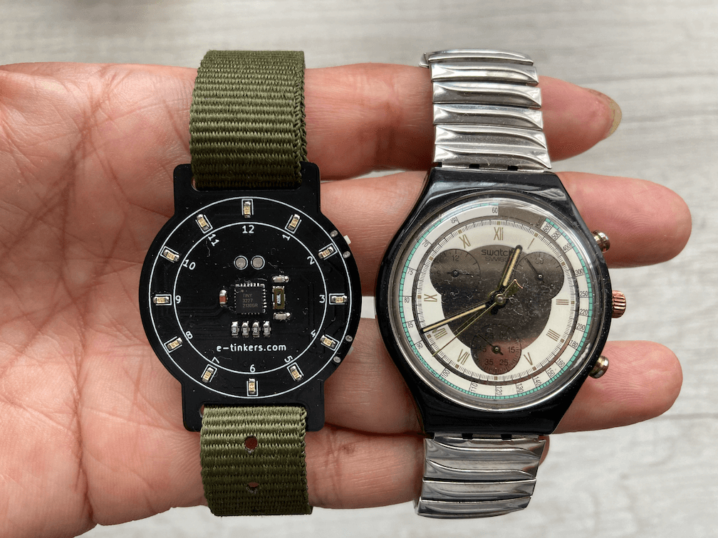
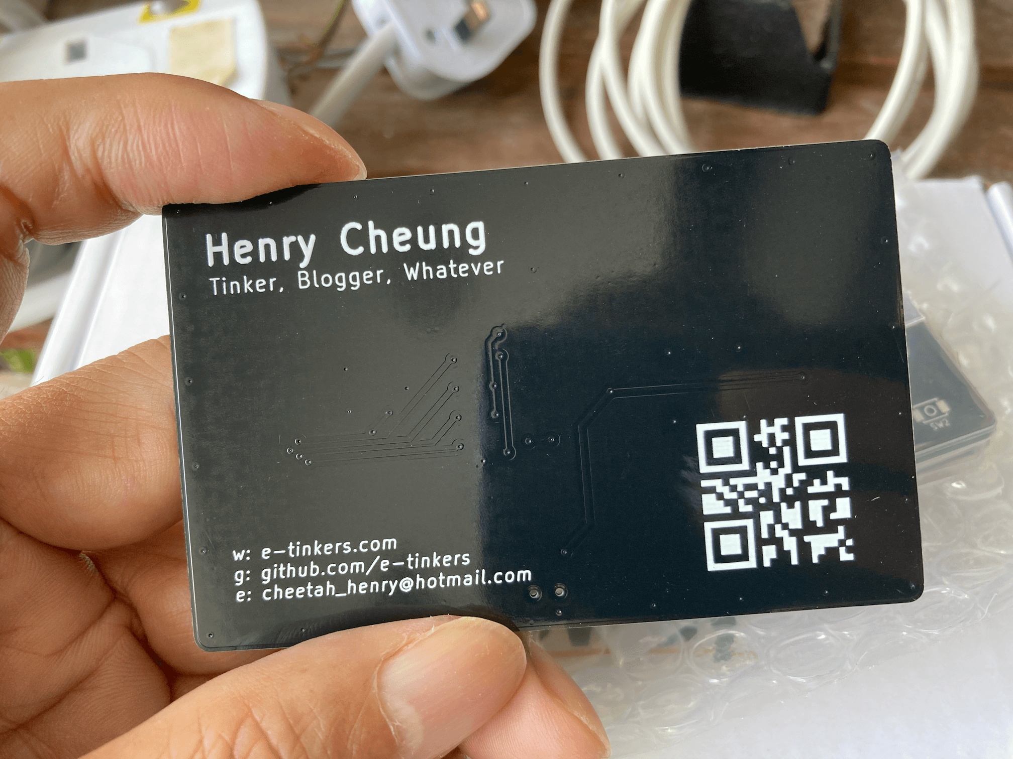
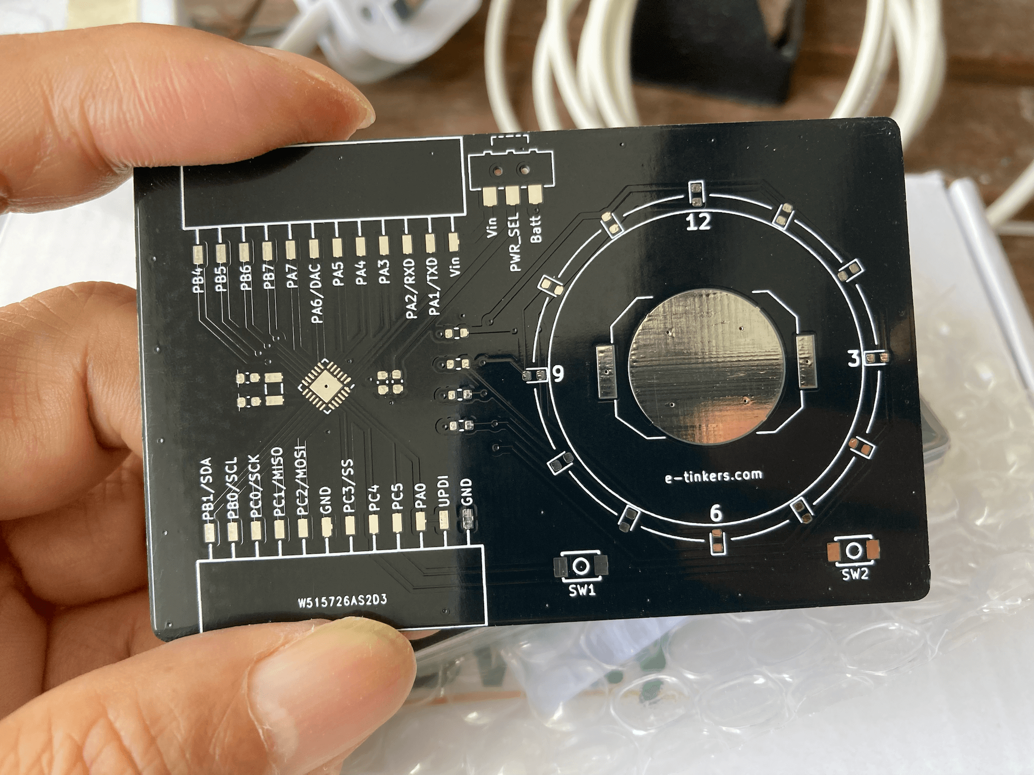
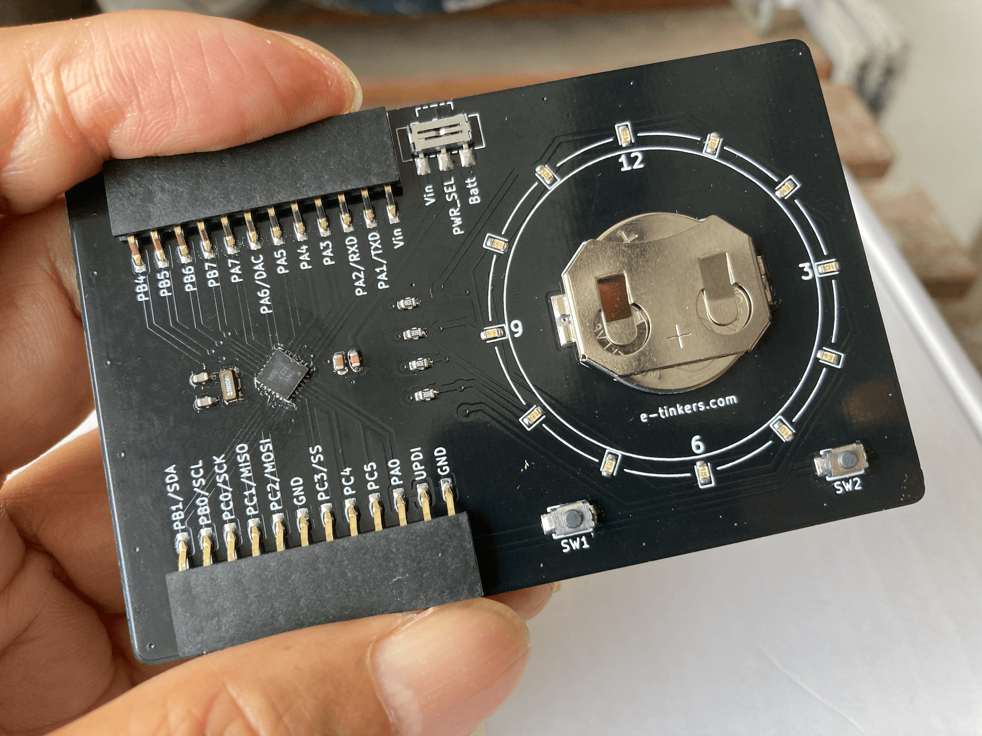
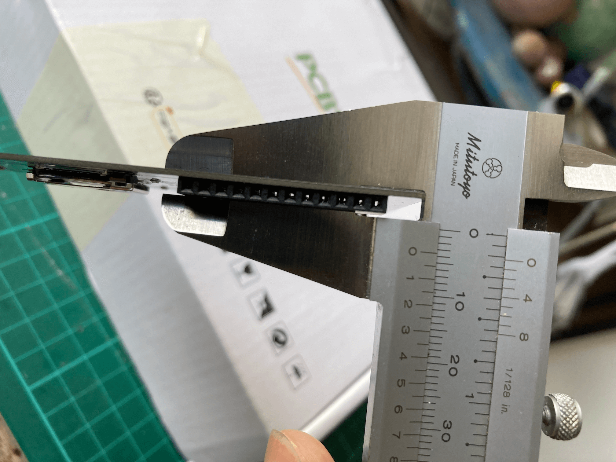
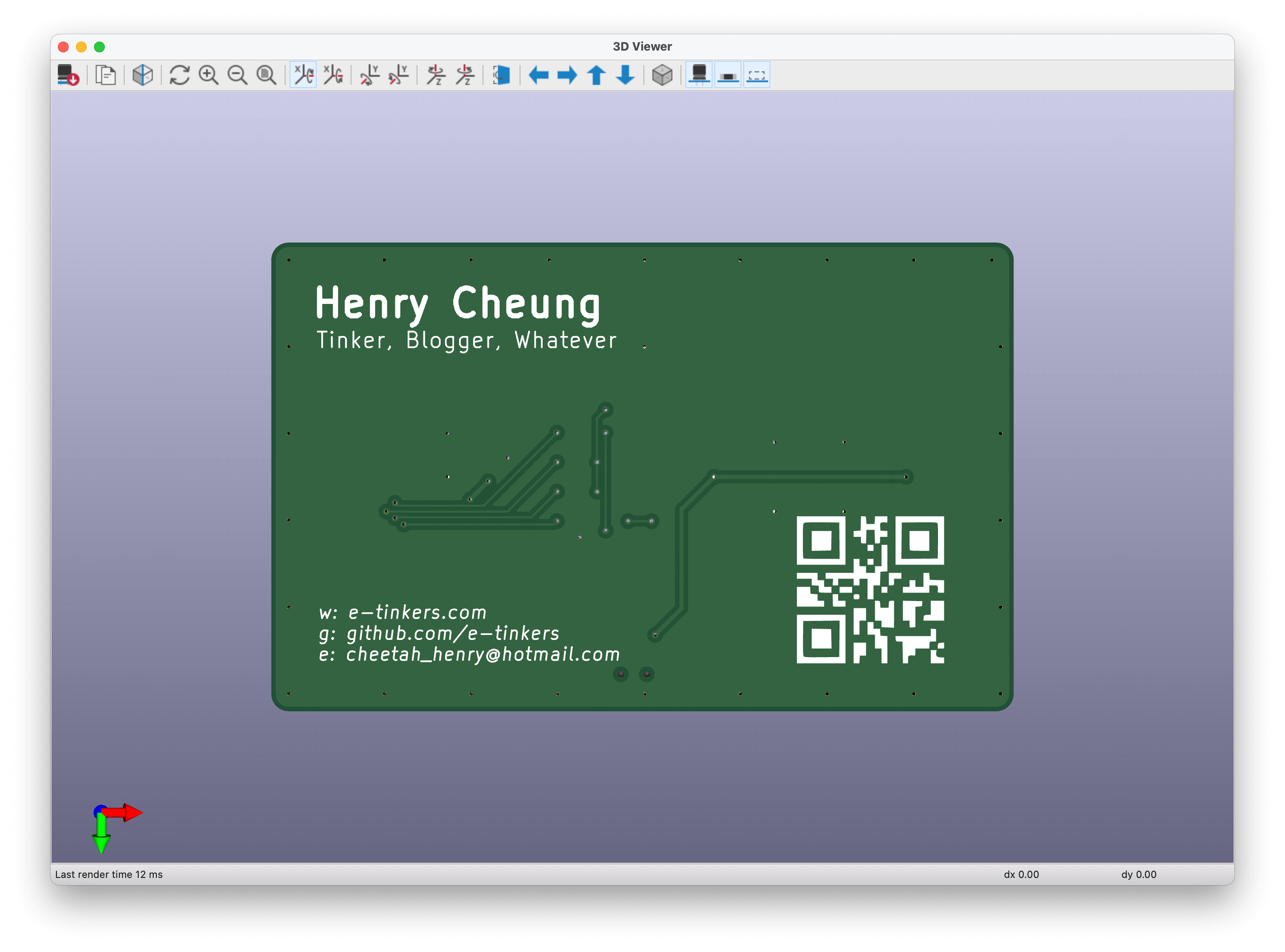
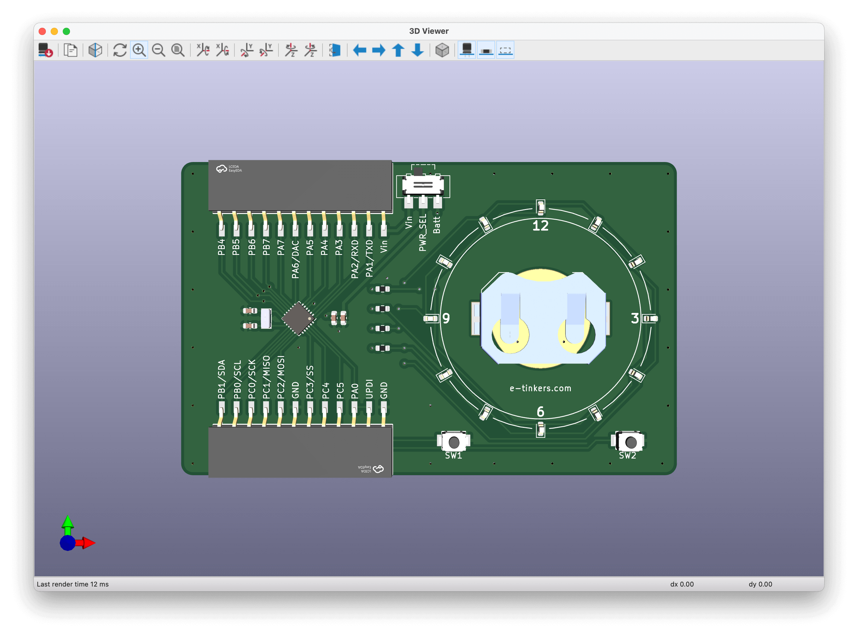
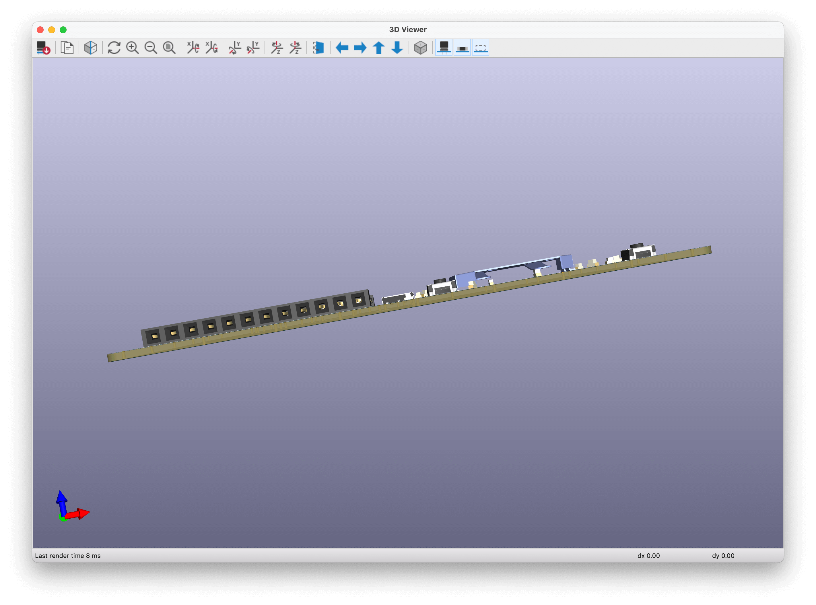
This project is a combination of the two projects, by replacing the power-hungry ESP-12 with a newer ATtiny3227, with PCB of a credit card/business card size, and the thickness of only 3.6mm (1mm PCB, plus the battery holder of a CR2016 of 2.6mm).


 Vishnu Mohanan
 Mike Szczys
 The Lightning Stalker
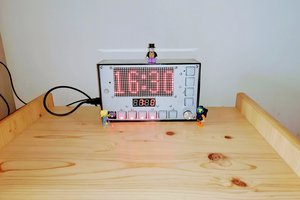
 Christoph Tack
Nice idea! Have you thought of using reverse mount SMD led's and having the clock show on front of the card? That'd enable you to keep it thin, but have the clock show in a more minimalist way...