Close
0%
0%

Adding aux video input to BetaFPV VR03 goggles

a 5 minute adventure to impruin your first FPV kit

Similar projects worth following
Have you just only started your journey into wonderful world of FPV but budget is tight and your options do not allow you to fly sim with your goggles but you wish you could do it as well because you've crashed your first build beyond recovery?

This guide has got you covered.

This project describes how to add analog input to your cheap FPV goggles to be able to connect external video source (like PC with sim launched, different VRX, you name it) which is not usually present on cheapest options.

Disclaimers:

- You WILL void your warranty.

- Author is not responsible for damage to your property, reversible or not.

- You may destroy your device permanently.

- Even if you successfully pull off whatever is presented here - you may be one static discharge away from ruining your equipment.

- Project includes working with sharp objects and LiPo batteries - use necessary caution.

- You have been warned.

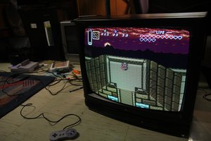
Final result to gain attention:


And some trivia after the break.

Read more »

  • 1
    Open it up

    Meet the victim: beginner-level FPV goggles from BetaFPV.

    Remove antenna, remove SD card, remove all visible screws so you will be presented with primary electro-optical block. You are interested in main electronic board:

  • 2
    Cut the trace

    Grab your knife and steady your hands before proceeding:

    I must warn beforehand that this is not the optimal way functionally, but this is the easiest for our purpose. 

    I've only figured out one trace that is easily accessible for cutting - and it leads from buffer/switch IC and to LCD controller to the right. 

    Splicing into this part will allow you to switch external signal to LCD, but you will not be able to record external signal to DVR - it will still record whatever VRX is tuned on. RSSI indicator will also only detect whatever VRX outputs. Feel free to probe around to see if there is a better way to cut VRX video output before doing your hack - maybe it is much easier than i thought.

    Now onto some surgery.

    You are interested in this trace over here:

  • 3
    Bodge it on

    Heat up your solder and make some prepared wire.

    You will solder one to VRX GND terminal, other wire goes to "To LCD" exposed copper area that was made bare in previous step.

    If you decided to have switchable solution - this wire goes to "common" switch pole. In this case you will also need to add another wire to "From VRX" and solder it on to one of the switch NO/NC poles so you will be able to select your current channel.

    Now for some miscellaneous notes.

    Initially I looked up for some markings of chips that i saw there. One was TVP5150AM1 decoder which had video input on its first pin.

    So naturally, i thought - this was it, because that passive circuit before it looked exactly like analog video input - it starts with 75 Ohm load resistor to the ground, then some filtering and then it ends up in this decoder chip.

    But when i cut it and tested if LCD displayed what i wanted - what saw there was that i made a mistake. It still diplayed whatever VRX was tuned on and when i tried to record DVR - SD card had a file that displayed what was fed through my added wire.

    And that is how i figured out that that whole area is actually DVR block (sure, as if SD card slot module was not enough).

    And that is how Bridge of Shame was born, before i probed around to find how switch IC is wired and mended that cut i've made before.

    Also, if you are feeling fancy, to switch a video signal properly - you will need a video multiplexer chip that is adequately buffered and has all the bells and whistles on it's inputs and outputs. There are readily available video switcher modules in RC hobby and they look like this:

    This will give you more clean signal (not that this solution does not) and properly saves every other involved part in the circuit from sudden static bursts and such. But these things, although cheap, also require additional control. These modules on the picture, for example, are controlled by either IBUS/SBUS signals, or by Servo PWM - which are available on RC craft, but for this project you will need to slap together something that outputs exactly that. And it also a powered circuit, that will put more drain on your already feeble FPV goggle tank.

    You can make goggles with servo tester module look cool, though - and it also totally works for video multiplexer modules for RC hobby. Twist that knob, beauty.


View all 6 instructions

Enjoy this project?

Share

Discussions

Similar Projects

Does this project spark your interest?

Become a member to follow this project and never miss any updates