 Thatcher Chamberlin
Since I started work on this project before I started the project page, this post will be to fill in the reader with what I've already done. I decided to use the LPC1114 chip instead of an Arduino (with which I'm more familiar) for a few reasons:
1. Its max clock speed is 50 MHz, about three times faster than an Arduino. Early experiments with my simulated computer version of this indicated that to achieve centimeter accuracy, I would need time measurements on the order to microseconds, so CPU speed is a top priority.
2. It's a DIP chips, which makes prototyping easy.
3. It's an ARM chip, which is something I hadn't used before. ARM chips seem to be the way of the future so I decided to dive right in with one on this project.
4. It has a *built-in* serial bootloader, so programming it is just a matter of hooking it up to an Arduino or similar with a UART.
After doing some research on blogs (these two were the most helpful), I was able to get the LPC1114 running on a breadboard using something similar to the schematic below. I'm using the online mbed compiler which works great and the program lpc21isp to flash the chip via an Arduino.
The other part of the initial design had to capture the vibrations from the piezo elements. Right now I've got the elements taped to a wooden table with their leads going to the connectors P1 and P2 on the schematic below. It took a lot of experimentation to get the current capture circuit. The two elements are connected to op amps acting as comparators with the threshold set by a potentiometer. At first, I had considered using ADC readings and cross-correlation to detect vibrations, but since speed is such an important factor, I opted for the comparator approach which outputs a high or low voltage depending on whether or not the input voltage (from the piezo element) is higher than the threshold. These outputs are connected the LPC1114 microcontroller's interrupts that triggered in the chip's code.
Once I had the microcontroller and the capture circuit figured out, I picked up a protoshield from RadioShack (it was even on sale!) and wired everything up. After a few false starts, I had a circuit that I could program and detected the slightest vibrations with. You can see it in the first picture I've uploaded so far and you can see its schematic right below here:
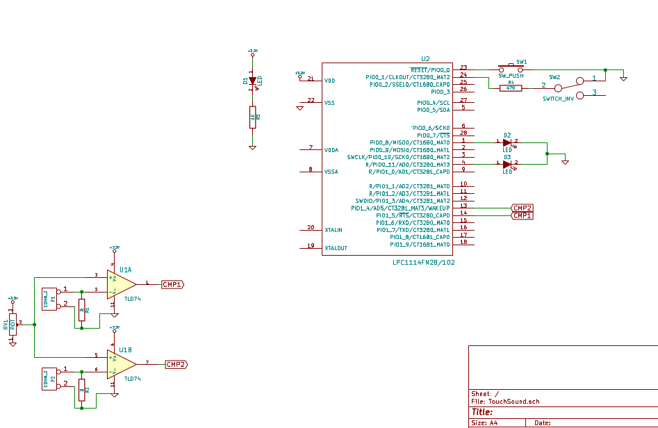
It's worth noting that while this version has only two op amp comparator units (on the bottom left), the final version will have three. I just couldn't fit the whole op amp on the protoshield :)
So that's the status of the hardware side of things. I'll do a log on the code I'm using in a day or so.
Thanks for reading, skulling, and following!
Discussions
Become a Hackaday.io Member
Create an account to leave a comment. Already have an account? Log In.