 Tom Anderson
"Anyone who considers arithmetical methods of producing random digits is, of course, in a state of sin." - Von Neumann
This project provides an analog means to create true-random numbers from the thermal noise of resistors. The circuit is easy to measure and verify.
The recent unpleasantness in privacy rights and security from eavesdropping emphasizes the importance of secure cryptography. Hard crypto, the cypherpunks would call it. Random numbers are a necessary ingredient in the larger problem of cryptography.
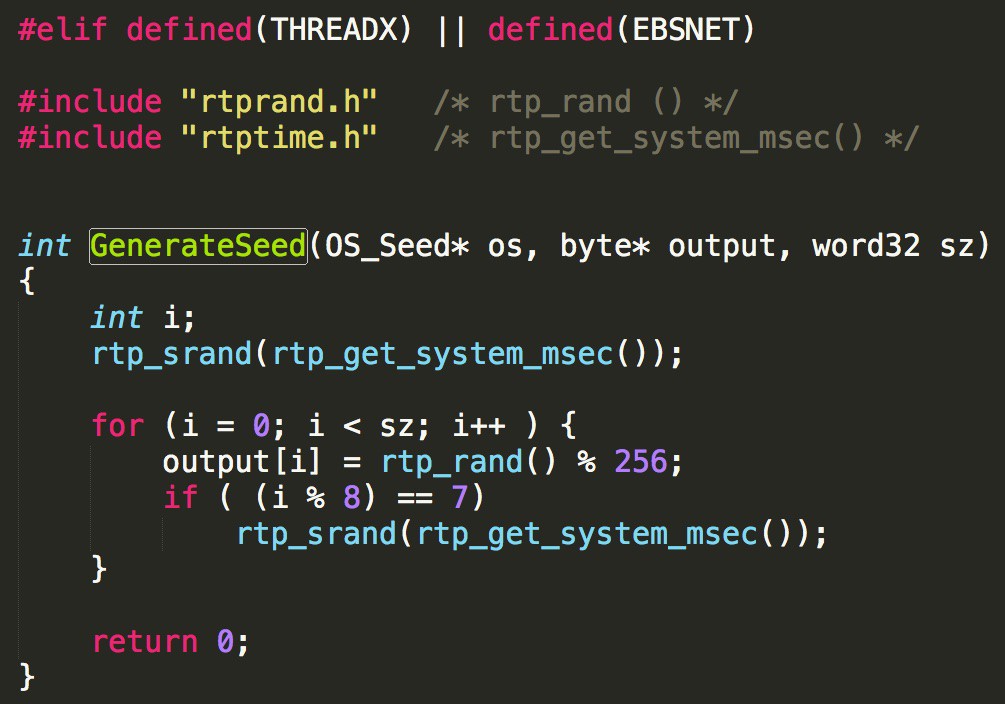
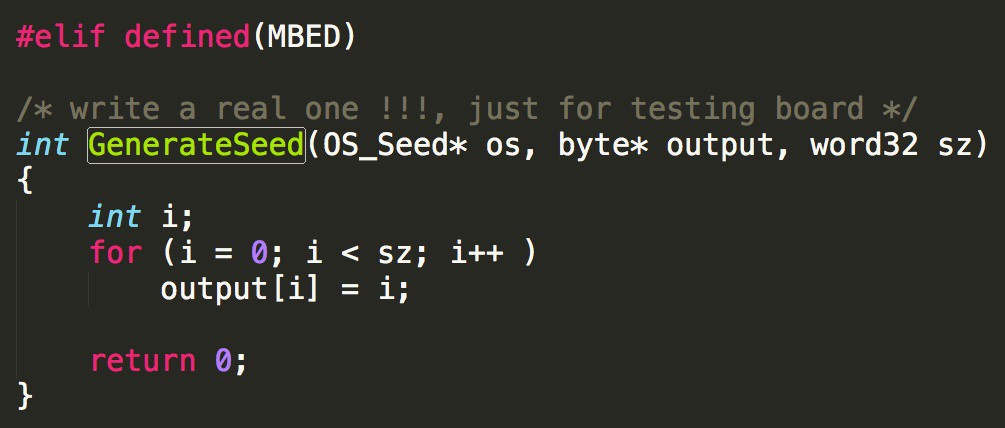
This project is somewhat similar to an existing product, the TrueRNG – Hardware Random Number Generator, which used to be available as a $50 USB stick. I don't think there is really much of a market for this type of device. The benefit from this design will come from it being incorporated into other products to make them more secure. For example, IoT devices should be running HTTPS, and yet they may not have a ready source of entropy from their random number generator. These numbers are (slowly) generated by the Linux Kernel and put into a 4k buffer. Sources of entropy in Linux for these devices is mostly limited to network traffic. This is not always a great way to do this, and is not done in all cases. Here example random number generators used to seed SSL from the CyaSSL library. It has #ifdefs for the various operating systems, since they vary with the available hardware:
Not good. Sinful, actually. Not as bad as this one, though:
Some processors have built-in random number generators that might be pretty good. Who knows? They can't be verified by the application designer.
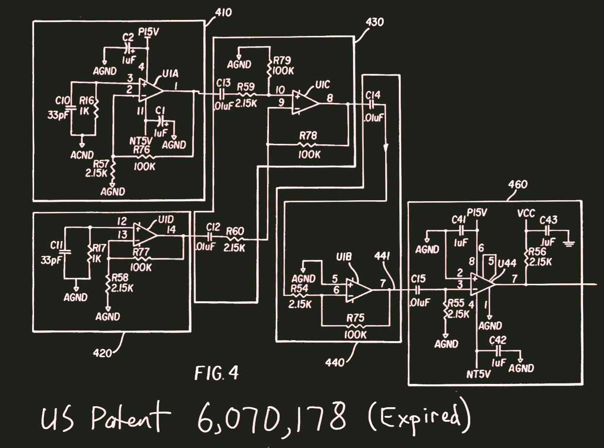
I designed this random number generator where the source of randomness is the thermal noise in a resistor:
My original prototype was hand-soldered to a 68HC11 board that had a prototyping area, using components from a local surplus store. I don't know where the board is now, but I might be able to find it and post a picture. I wrote code to send the random bits out the RS-232 port, which I connected to an HP-735 workstation. I wrote test code for verifying that the output data is random. These days, there is more code available for that purpose.
The patent was assigned to a startup, who embedded it into a crypto product. The startup dissolved and they did not pay the renewal fee. This irrevocably ended their rights to it, and the circuit can be freely copied. This will take care of the analog section of generating the numbers. For this project, I am going to have to create a new digital interface, since apparently the 68HC11 is no longer in vogue. I checked, and there are a few parts left on Digi-Key! But I have thrown out my paper copy of the Pink Book.
I got a discount offer from AutoDesk for the Standard Version of EAGLE, and paid $50 for a 1 year subscription. The offer was because I have a free account on circuits.io. I like the EAGLE XML file formats for schematic and layout, so I had wanted it anyway. I took an EAGLE class last year from Matt Berggren, and today I watched some refreshers on YouTube (part1) (part2) (part3) by Jeremy Blum. If I don't like EAGLE, I'll probably try KiCAD again. If anyone wants to help with the project and has strong feelings about which tools to use, I am open to suggestions.
I created a project github repo. The EAGLE files are there under revision control, along with any firmware and application software. The name of the repo is true-rng. The license is BSD.
When talking with people about the circuit online and at meetups, there are some common questions:
What is new about it?
I have recalculated the design, with all new the signal levels and bandwidth. I used modern surface-mount components, and created a new layout. There was no existing open version of this design to start from.
The first big change was to the power supply. I have made non-trivial changes: The old design required a positive and a negative supply, and the new design uses a single supply. Creating a low-noise design with a single supply is a challenge. The new version of the circuit has a 2.5V power supply where I had a ground plane in the original. This new supply needs to be extremely low noise, and there is some risk that the this will not work. However, if I do get it to work, it will prove that I can design low-noise circuits with a single supply.
Resistors generate noise? Really? Where can I learn more about this?
To get started, see this Wikipedia article Johnson–Nyquist noise. If there is sufficient interest in this circuit, I can also make a video about how to calculate the noise levels in an analog circuit. After you learn how to do it, many circuits can be solved approximately and intuitively by inspection, much like simple voltage divider or opamp circuits. The noise calculation will also help you understand oscilloscope measurements and communication receiver architectures. Oscilloscopes have a wide bandwidth, which means that they have a relatively high noise level. Communication receivers reduce the bandwidth (one way or another) and minimize noise.
Other than making random numbers, what are the uses for this circuit?
There are a lot of sensor designs in IoT devices that could be improved with low-noise design techniques. Learn how low noise design from this circuit, and leverage it for sensor applications. This circuit shows how to process 20uV signals from a 100kOhm impedance while keeping a good signal to noise ratio. Sensor circuits often use a Wheatstone Bridge configuration that is similar to this circuit.
How do you know that the noise is coming from the resistor, and not somewhere else?
The design equations in the spreadsheet (xlsx file included) predict the noise levels throughout the signal path. By adding a parallel resistor to the noise resistor, I can reduce the noise level by a predictable amount. The ability to predict and adjust the noise signal level with the resistor assures that the resistor is being measured, not voltage or current noise in the opamp, or some interfering signal.
What is the signal level of the resistor noise?
The noise level is 21uV RMS. The circuit amplifies and limits the noise signal to a 1 bit logic level.
How big is the board?
The circuit board is 44mm X 54mm (1.725" X 2.125"). It has four mounting holes in the corners that fit M3 or #4 screws.
How is the board powered?
A USB connector provides a 5V supply. This supply is doubled and then regulated and filtered to provide a precision 2.5V and 5V supply.
Why use a switched-capacitor boost supply instead of an ordinary PWM boost converter?
The boost converter will have an inductor that radiates a magnetic field that is difficult to shield. I want to have the lowest radiation possible. Most switchers use PWM to control the output voltage. Very small changes in power supply current can be detected by carefully demodulating the duty cycle or frequency of the PWM. This could potentially leak information about the random bits being created. The switched capacitor converter is a fixed ratio and not a PWM.
The magnetic field from a DC to DC converter circuit tends to leak into nearby oscilloscope probes. The inductance formed by the loop of the probe's ground clip tends to pick up the field.
The voltage ripple from a DC to DC converter is relatively well-controlled, and the filtering and voltage regulators should attenuate the ripple by a known amount. Although I haven't documented this yet, I have kept track of the supply ripple as part of the design process. Designing enough shielding and ripple reduction for PWMs with inductors in low-noise circuits requires a lot of design and testing. I have had good first-pass results with switched capacitor circuits in previous designs.
Why use resistors as the noise source instead of diodes, which have a higher noise level and are easier to amplify?
I have used diodes in sensitive analog applications and they are full of surprises! Resistors are much better behaved.
It is easy to verify that resistors are creating true thermal noise in accordance with well-known physical laws. Simple oscilloscope and volt meter measurements are all that is required. Many noisy devices such as diodes, transistors, and thick-film resistors have 1/f noise that is not flat with respect to frequency, and this noise level varies from device to device. This is one reason why the design uses precision thin-film resistors instead of the cheaper thick-film.
It is true that diodes can be more noisy. However, there is no guarantee of what the exact noise level should be, or that the noise will not have a pattern. For example, I could easily design an IC/diode that behaved exactly like another diode, except that it creates a random-looking, but really not-random, signal instead of noise. If this part was installed in the random number generator, there would not be an easy way to know that the numbers were not random.
Why not use a whitening function such as SHA256?
An application or random numbers might benefit from a whitening function. The purpose of the random number generator is to create a well-known amount of randomness that is based on well-characterized and understood physical processes. Entropy + SHA256 is not equivalent to more entropy, because it assumes that SHA256 is not reversible. Historically, people who design this sort of algorithm have sometimes included a secret back door that makes the function more easily reversible. Using something like SHA256 also requires the user to trust the person who developed the SHA256 code and algorithm to have done it correctly, and also to trust that the algorithm works as advertised. The purpose of the project is to create random numbers that are verifiable based on physics, not a trust relationship.
Why not just use SHA256 to create a pseudo random number generator, just by incrementing a counter and concatenating with a seed?
This approach falls under the category of "not good uses for SHA256". I first learned about challenges with random numbers when debugging problems in a Monte-Carlo circuit simulation that used a similar approach. As Von Neumann said, "Anyone who considers arithmetical methods of producing random digits is, of course, in a state of sin."
Are you going to make a business out of it? Do you want to quit your day job?
No, and no. I have dabbled in cryptography and I like thermal noise but it is a hobby. I already have a cool day job. I do enjoy looking at other people's analog circuits, though, so let me know if you need help. Keep in mind that I will tell you that you need a ground plane, so if this is a non-starter for you, please don't ask.
Where are your future plans for this project?
If there is sufficient interest and funds, I will have the board built, get the parts, load it, and then make it work. Or I might try a low-cost proto shop, or see if my friends at Tempo Automation want to build it, or ask another friend who has a pick-and-place machine. After that, the next version of the design will turn the random bit stream into USB format so that the noise generator can be used as a peripheral. I can prototype this using an Arduino or other microcontroller.
There is also a possible miniaturization step. Right now I am using wide traces and relatively large (0805) resistors to make rework easier. The board could be quite a bit smaller, but then it would be harder to build and work on.