 Rene
ReneOverview
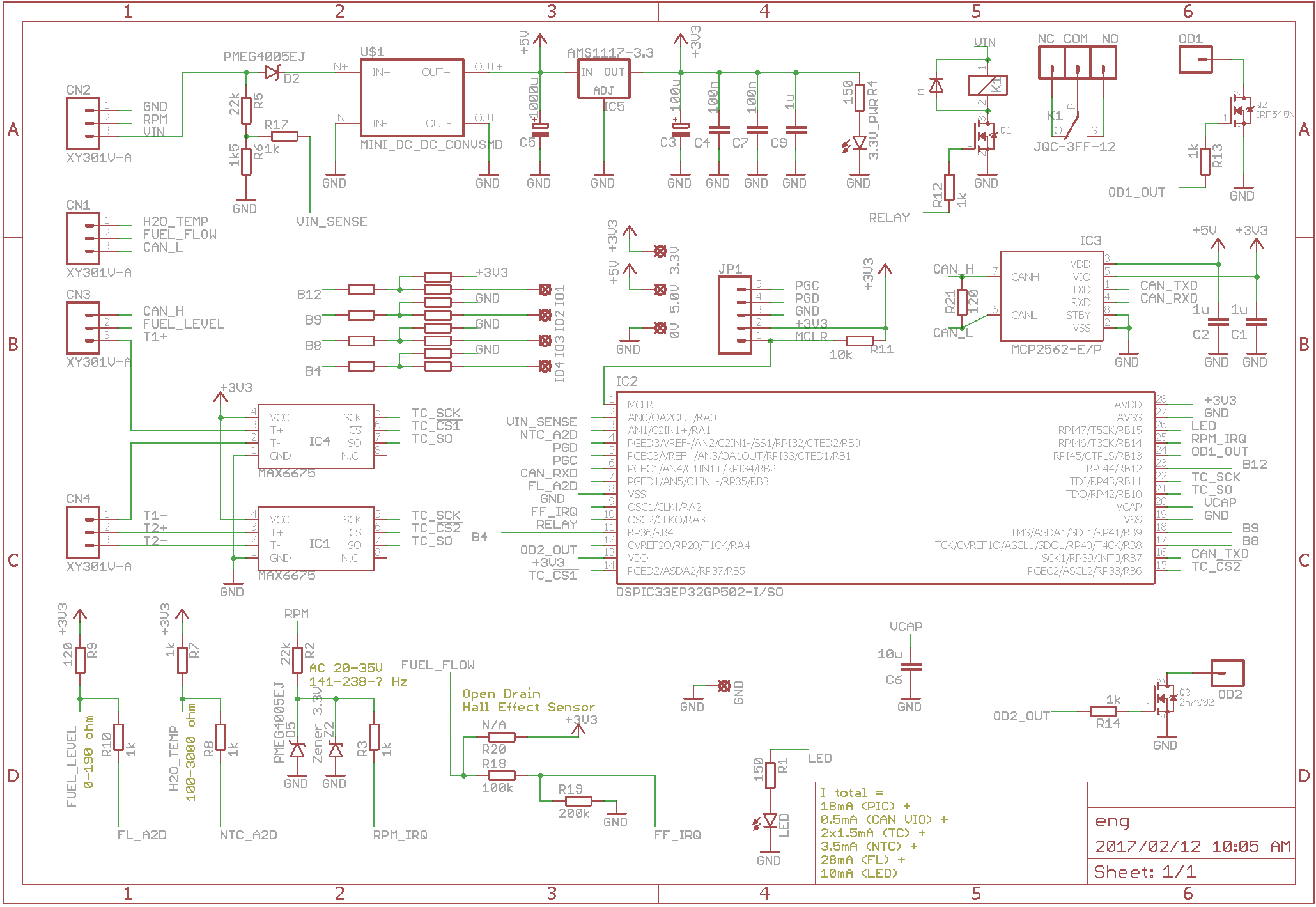
The diagram below provides an overview of the module:

Features:
- Bus Voltage Measurement
- EGT Thermocouple 1
- EGT Thermocouple 2
- Engine RPM
- Engine Hours / Hobbs Meter
- Engine On Time since started
- Maintenance Timer
- Fuel Level
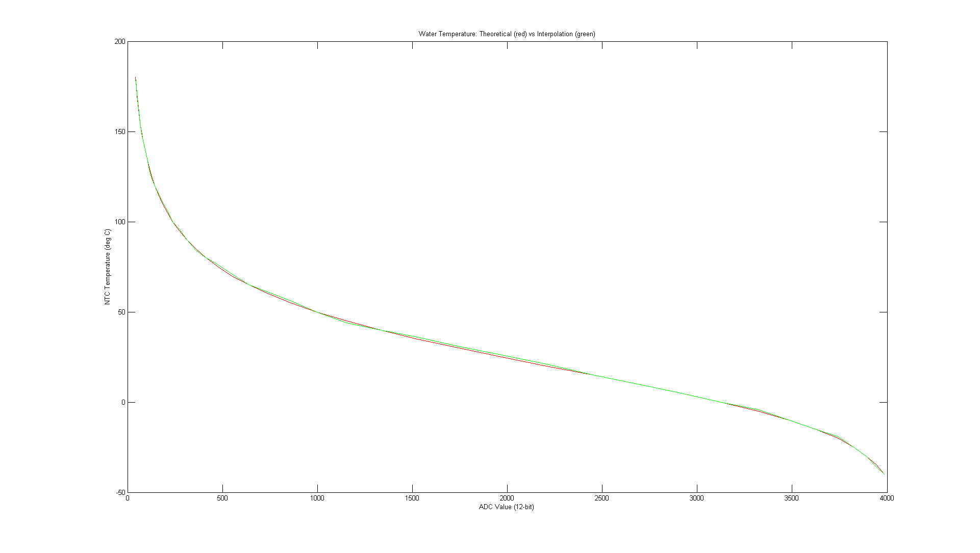
- Water Temperature
- Relay Output
- Open Drain 1 Output
- Open Drain 2 Output
- Fuel Flow Instantaneous
- Fuel Flow Average since started
- Time to Empty Tank (fuel endurance)
- Range to Empty Tank (fuel range)
- Fuel Burned
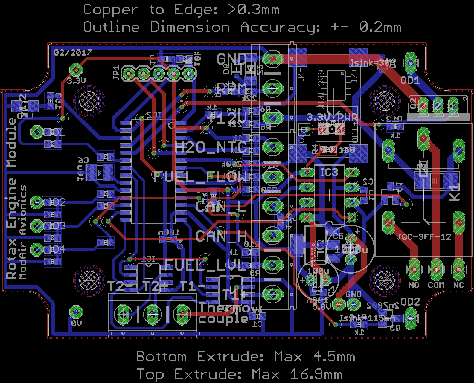
Schematic and PCB
The schematic is shown below. Source files are in the GitHub repository.
Mechanical
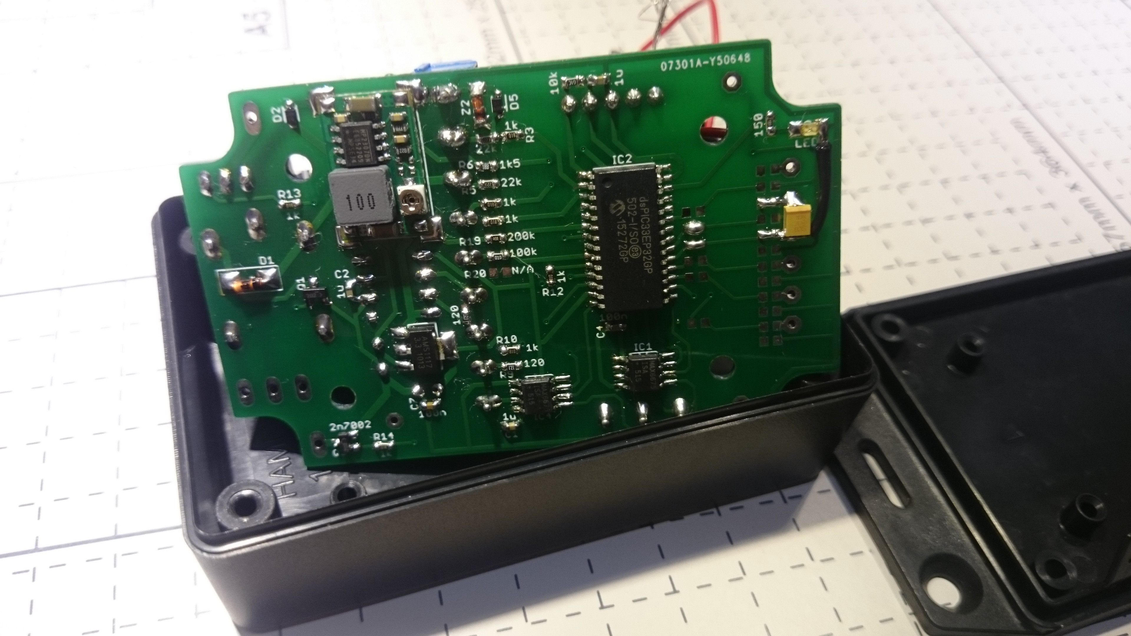
I designed the engine interface module PCB to fit into the Hammond 1591 ABS Flanged Enclosure (86.24 x 57.04 x 24.25mm, RS Stock no.: 818-0523).
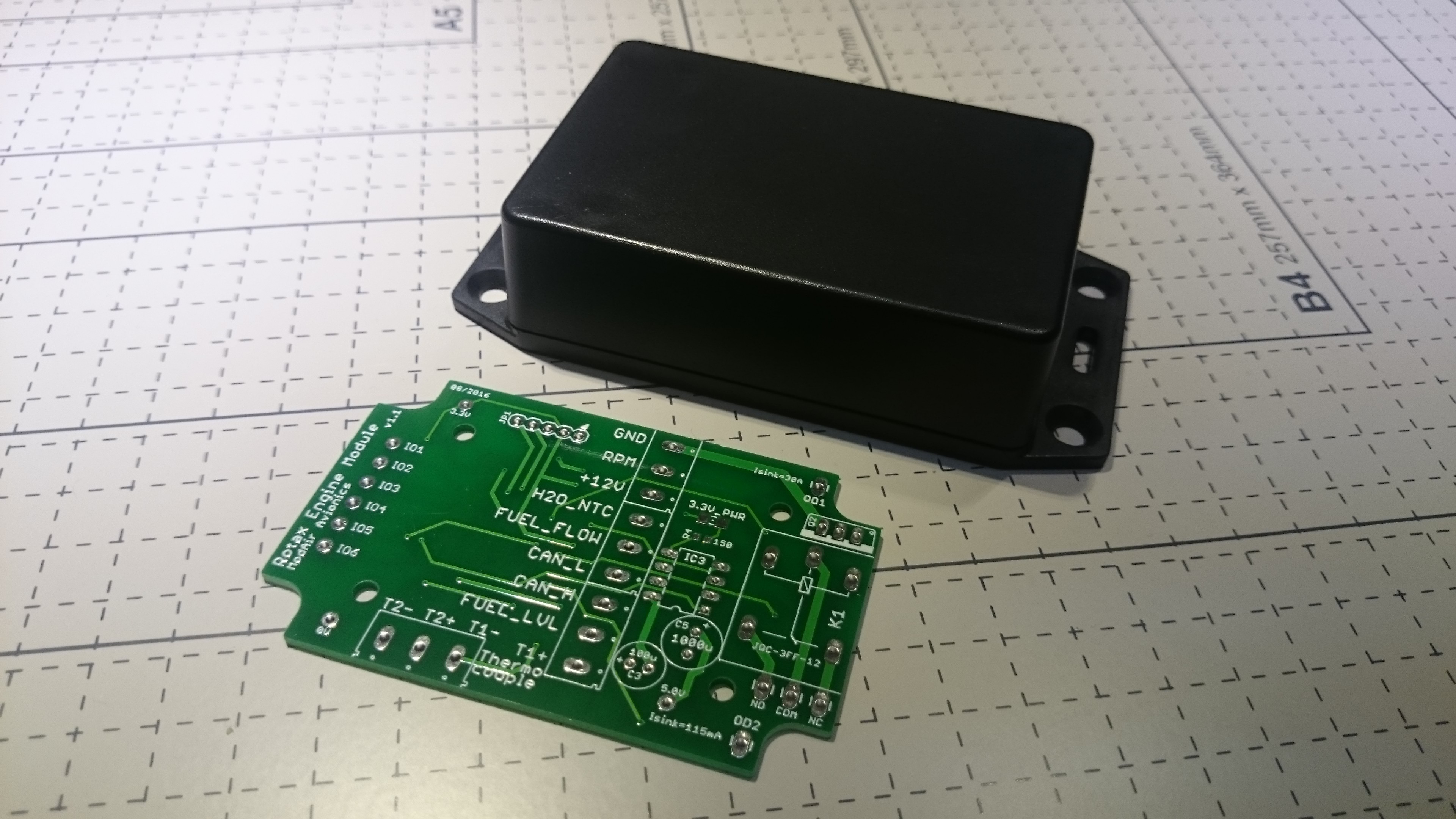
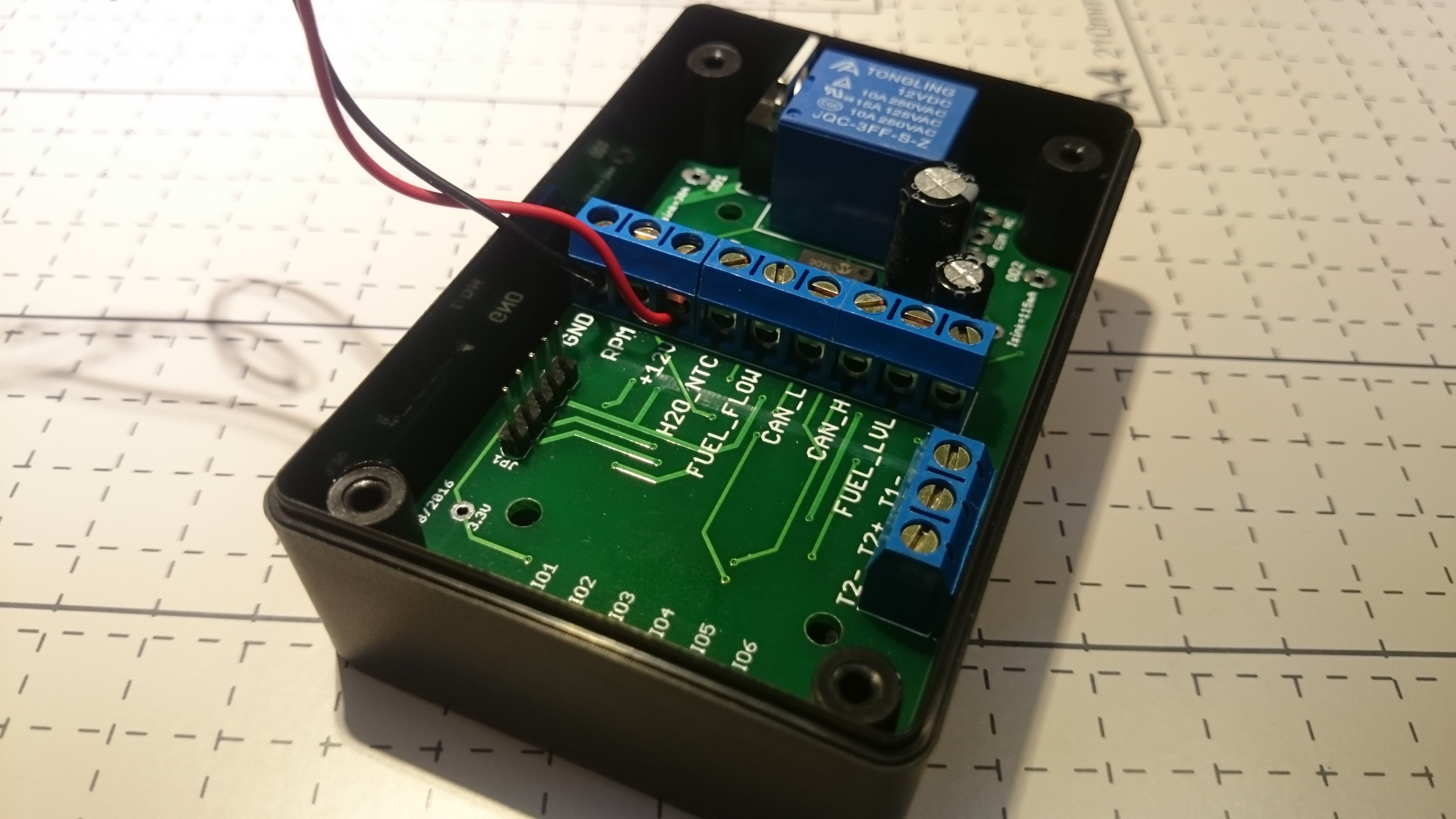
Pictures after assembly are shown below:

 matthewreed
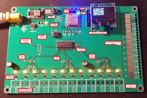
 Red Tuka
 Coders' Cafe
 Aula Jazmati